Orthopedic knee crutch

a knee crutch and orthopaedic technology, applied in the field of orthopaedic knee crutches, can solve the problems of limited movement on the body, limited mobility in confined spaces, and difficulty in using crutches, and achieve the effects of reducing increasing static friction coefficients, and reducing the sliding and slipping of crutches

Inactive Publication Date: 2007-11-01
MOORE MARK
View PDF12 Cites 18 Cited by
  • Summary
  • Abstract
  • Description
  • Claims
  • Application Information

AI Technical Summary

Benefits of technology

[0008] An orthopedic knee crutch employs distribution of centerline weight loading by means of horizontal feet that are both symmetrically and asymmetrically attached to a lower end of the crutch assembly to provide a stable device. The horizontal feet, each preferably include durable elastomeric tips that increase a coefficient of static friction between the feet and the surface upon which they rest. This increased coefficient of friction advantageously minimizes sliding and slipping of the crutch during use. The horizontal configuration of the feet incorporates multi-contact points with the ground surface in a selected manner for improved stability, as opposed to single pod contact of a traditional crutch. Moreover, the preferred arrangement of horizontal feet allows the instant device to maintain an upright position when not in use. A lower vertical riser support assembly facilitates full body centerline loading during knee placement during use of the device.
[0009] A distance between the feet and knee contact point is adjustable to accommodate users of various heights. The invention includes an adjustable, detachable ambidextrous cushioned knee pad and an upper vertical riser support assembly that accommodates the transformed centerline loading as imparted by bearing of the direct body weight from the user's hand. A rotatable grip attaches to the upper vertical riser and includes an arm length adjustment means for adjusting the height of the grip relative to the feet of the device. An ergonomic grip handle assembly includes offset bends and is configured to facilitate the aforementioned transformation of the user's hand bearing load into direct centerline loading that is delivered onto the lower vertical riser assembly to be imparted onto the horizontal feet. The adjustment means of the handle grip assembly allow the handle to be rotated to change from right hand to left hand use. Both vertical riser support assemblies include adjustment means for adjusting the height of the handle grip and the knee pad. Preferably, each vertical riser support assembly includes two adjustment means which provide an infinite number of adjustment heights.
[0010] It is an object of the invention to provide a superior medical device for assisting with walking, standing, or resting of the lower leg, ankle and foot in those persons with debilitating conditions that would otherwise preclude the normal load bearing activity incurred during standing or walking.

Problems solved by technology

The crutches can be difficult to use.
For example, they limit mobility in confined spaces while requiring substantial strength and practice to use when transferring from a sitting position to a standing position and subsequent maneuverability during walking.
Other drawbacks associated with the use of crutches are: the limited movement on the body above the waist; the difficulty in bending or rotating the upper part of the user's body; induced pain as a result of load bearing on the sensitive area of armpits which are not conducive to supporting a user's weight for extended periods of time; and, crutches require the use of both hands during walking.
Moreover, crutches may be dangerous when used in slippery conditions.
Thus, they contribute to increased instability during contact with normal ground surfaces, and to an even greater degree with soft or slippery ground surfaces.
Other dangerous conditions created by crutches are that they become significantly unstable and difficult to maintain balance during transcending and descending stairways.
Thus, they require the user to have to prop them against something else or lay them down which therein requires more effort in the retrieval process.
Moreover, they do not facilitate the means of elevating or providing a “footstool” type resting benefit for the lower leg, ankle and foot when the user is seated.
They also require the user to support the entire weight of the lower leg, ankle and foot during standing and walking, and are not designed for use during bathing, showering or such activities involving the use water.
None allow for a no-hands operational capability during standing.
Nor do these devices provide for increased ground surface bearing area and permit the user to test the surface ahead for adequate or safe placement before subsequent full loading of the device.
They also fail to provide for full body weight centerline loading and preclude the transmission of bi-lateral loading on the user while allowing for use without the need for straps or other inconvenient means as an attachment to the user.
The prior devices also fail to provide the clinical benefit of lower leg, ankle and foot elevation during sitting.
Nor do these devices have multiple horizontal legs strategically positioned such as not to interfere with the normal walking stride of the user.
None of these devices incorporate a simplistic design as to preclude the need for any above-the-waist parts which would otherwise interfere with upper body movement.
They also do not contain a handle grip assembly fabricated in a manner allowing for direct centerline loading that minimizes eccentric reaction loads which contribute to decreased stability, while employing a simplistic design that allows for self-standing of the device.
They are typically bulky and interfere with a user's ordinary enjoyment during travel and are difficult to use in small rooms, cluttered areas, narrow pathways, and stairways.
The devices are not well suited for stand-up bathing activities that maintain the user's stand-up height plane as it were before any debilitating condition existed.

Method used


Image

  • Orthopedic knee crutch
  • Orthopedic knee crutch
  • Orthopedic knee crutch

Examples


Embodiment Construction

[0031] The present invention is ambidextrously designed, the detailed descriptions of preferred embodiments and their use are identical regardless of orientation. However, for ease in understanding the invention, the views shown in FIGS. 2A-2C, 4A-4C depict the invention configured for use with respective legs. These views when taken in conjunction with the exploded views of FIG. 6A-6C, aid the skilled artisan in appreciating the ambidextrous nature of the invention.

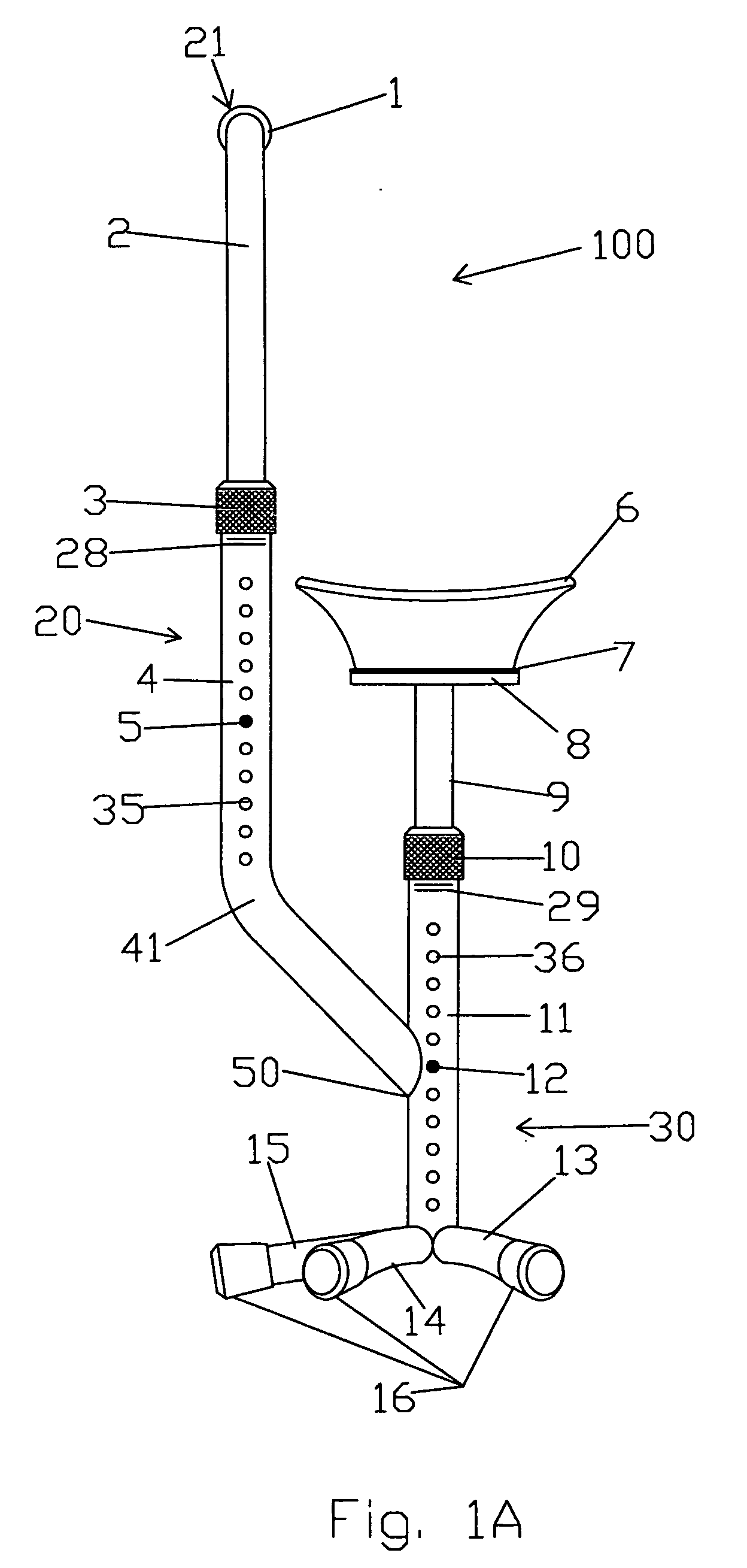
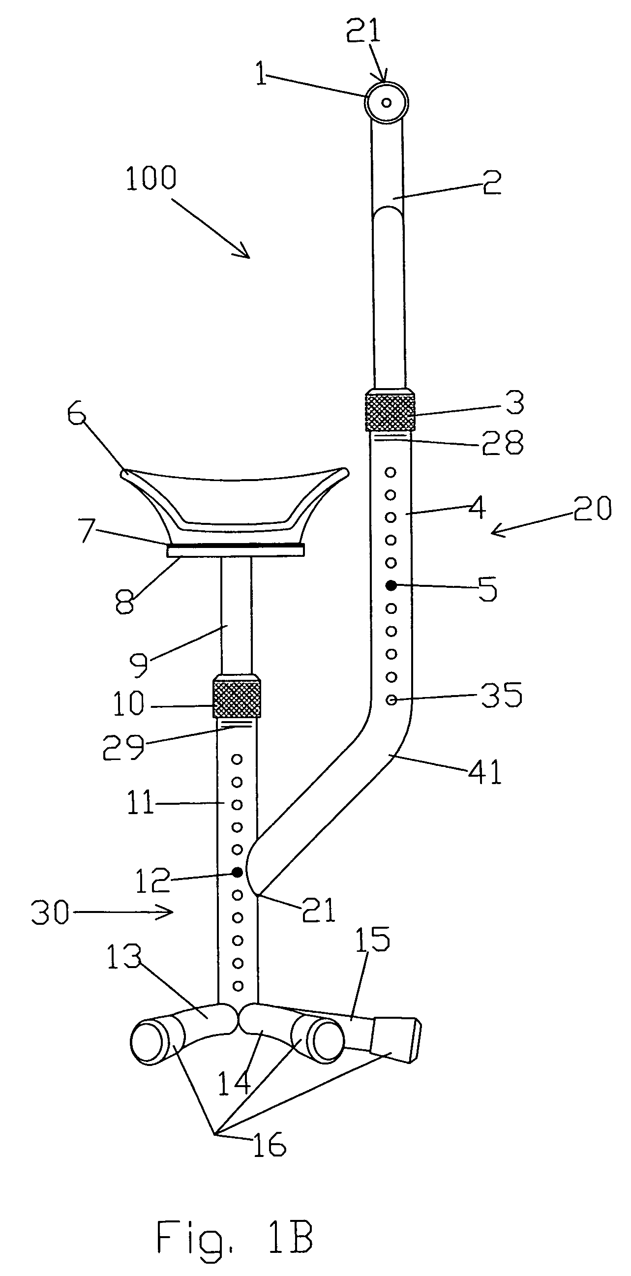
[0032]FIGS. 1A, 1B and 2A-2C reflect an embodiment of the invention configured for support of an injured right leg. FIGS. 3A, 3B and 4A-4C reflect an embodiment of the invention wherein the invention has been configured for support of an injured left leg.

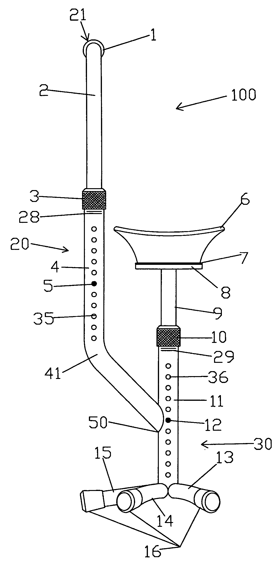
[0033] The knee crutch 100 of the present invention includes an upper vertical riser support assembly 20 and a lower vertical riser support assembly 30. Upper vertical riser support assembly 20 includes the upper inner tubing 2 and the upper outer tubing 4. One end of ...


PUM


Abstract

A self-standing, orthopedic knee crutch includes an ambidextrous cushioned knee pad attached to an upper end of a vertical support member that employs centerline distribution loading to transfer the weight of a user onto a plurality of horizontal legs that distribute a user's weight. Each horizontal leg includes an elastomer tip for increasing a coefficient of friction between the knee crutch and the ground surface to minimize sliding or slipping. An adjustable, rotatable handle extends upward and away from the vertical support member to aid in supporting the weight of the user.

Description

[0001] There are no related patent applications. [0002] This application did not receive federal research and development funding. BACKGROUND OF THE INVENTION [0003] This invention generally relates to a durable medical equipment for use in redirecting static and dynamic loads in a leg of a user in situations such as post-operation convalescing interims, congenital disorders, and temporary or permanent disorders that impair normal functionality of the lower leg, ankle and / or foot. More specifically, the invention is an ambidextrous, adjustable knee crutch that employs a practical solution for such persons having impairments that limit the normal weight distribution on a lower leg that results from standing and walking. [0004] Devices heretofore include crutches which include an armpit rest covered in a foam pad. The crutches can be difficult to use. For example, they limit mobility in confined spaces while requiring substantial strength and practice to use when transferring from a s...

Claims


Application Information

Patent Timeline
Patent Type & Authority Applications(United States)
IPC IPC(8): A45B5/00
CPCA61H3/02A61H2003/0205A61H2003/005
Inventor MOORE, MARK
Owner MOORE MARK
Why Eureka
Try Eureka