
Non-Contact Power Transmission Device

a power transmission device and non-contact technology, applied in the direction of transformers/inductance details, transformers, inductances, etc., can solve the problems of difficult to increase the coupling coefficient and interfere with peripheral electronic devices, so as to improve the transmission efficiency, reduce the size of the device, and less distortion

Inactive Publication Date: 2007-11-01
HOKUSHIN ELECTRIC
View PDF13 Cites 65 Cited by
  • Summary
  • Abstract
  • Description
  • Claims
  • Application Information

AI Technical Summary

Benefits of technology

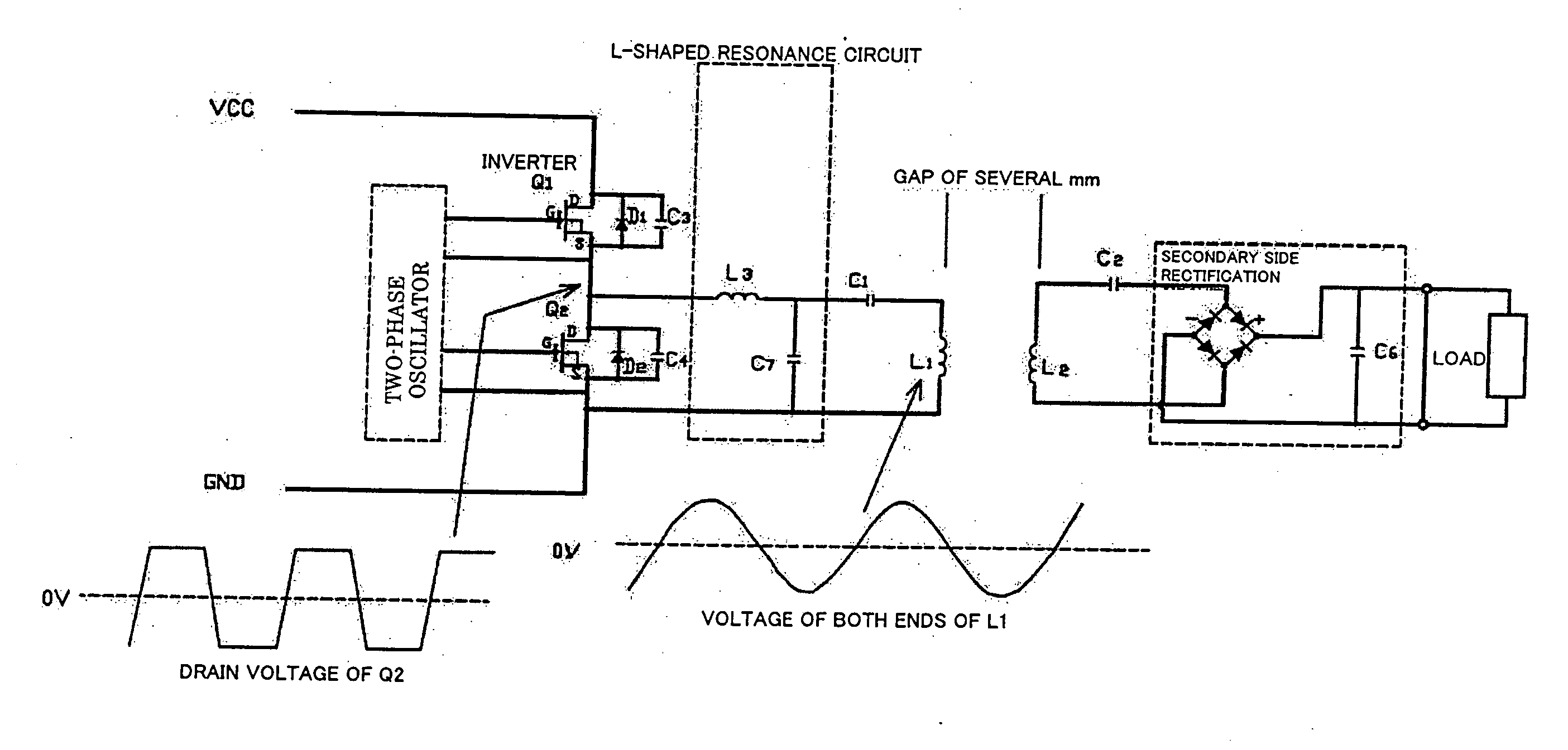
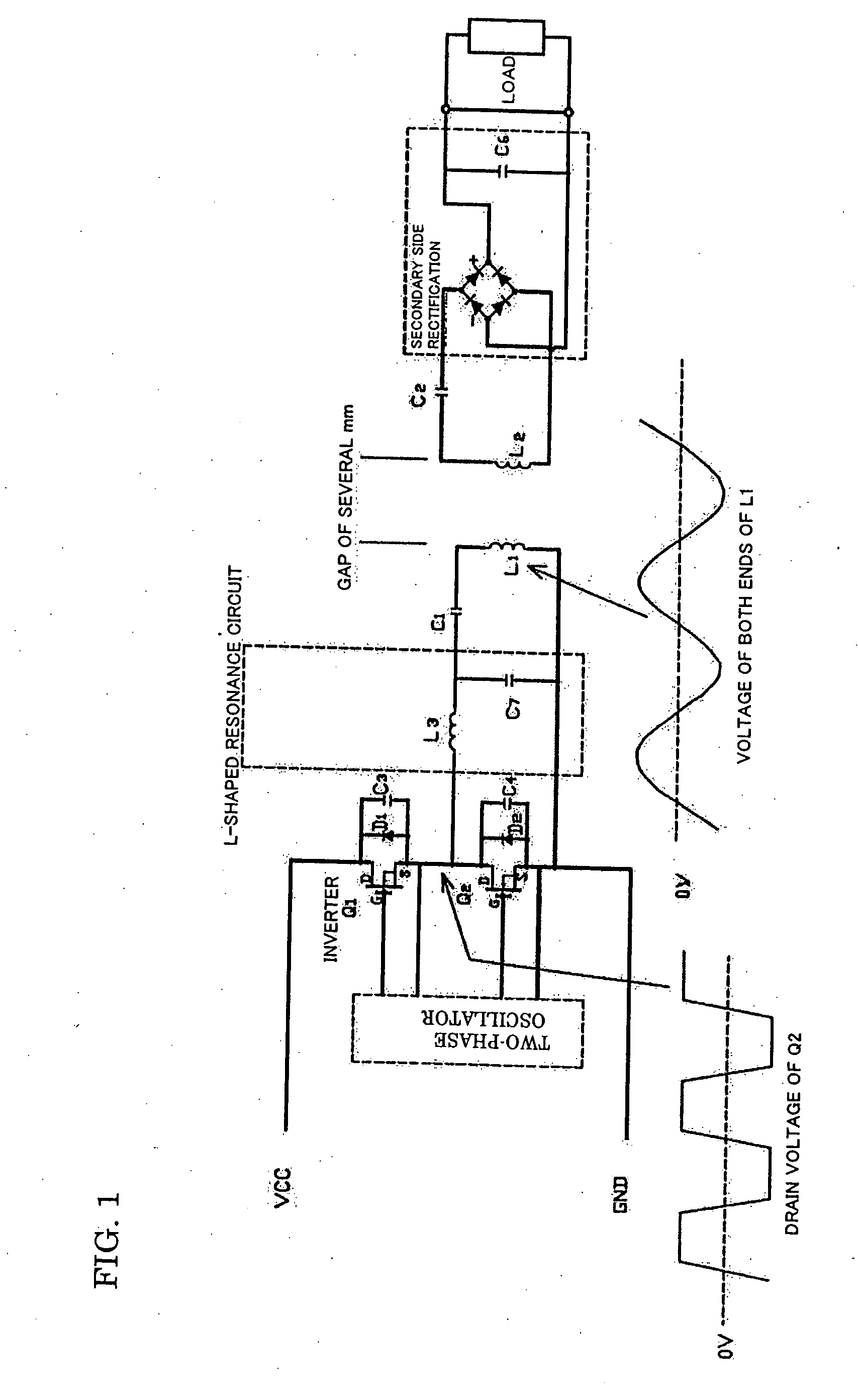
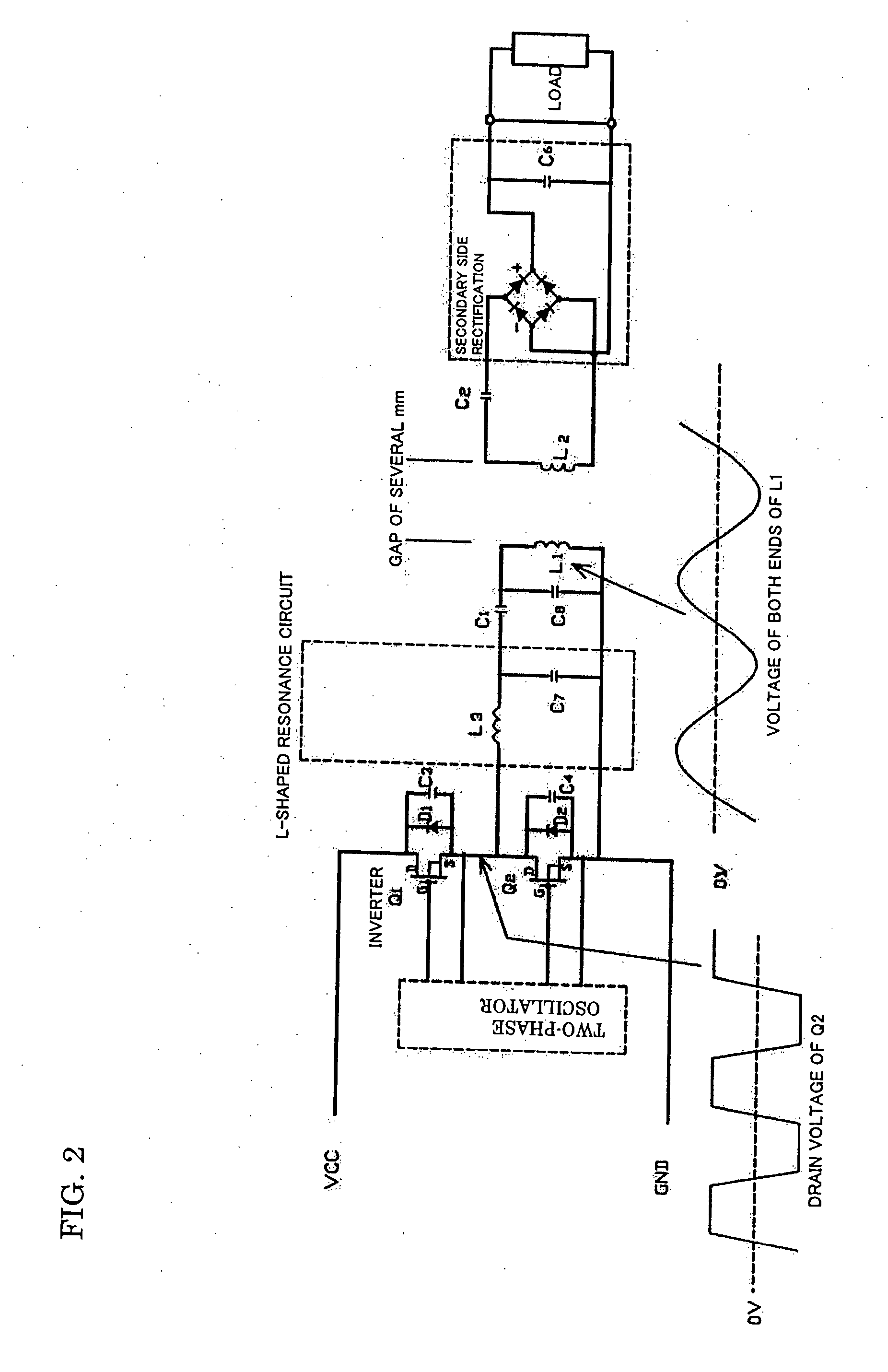
[0031] According to the present invention, the series resonance circuit is provided to the primary side or both the primary and secondary sides, thereby improving the transmission efficiency and reducing the device size.
[0032] Further, when the primary side series resonance circuit including the primary side coil is connected to the L-shaped resonance circuit in series, the rectangular wave driving voltage from the high-frequency inverter can be converted into the sinusoidal voltage waveform with less distortion on the primary side coil, thereby reducing the unnecessary radiation of the harmonic component from the primary side coil to space.
[0033] The non-contact power transmission device of the present invention is effective in high power transmission.

Problems solved by technology

However, when a gap between a primary core and a secondary core of the coupling transformer is close to 10 mm, it is not easy to increase the coupling coefficient.
Further, when the primary side of the coupling transformer is driven by a rectangular wave, a harmonic component is unnecessarily emitted from the primary side coil L1 of the coupling transformer to a space, thereby possibly interfering peripheral electronic devices.

Method used


Image

  • Non-Contact Power Transmission Device
  • Non-Contact Power Transmission Device
  • Non-Contact Power Transmission Device

Examples


Embodiment Construction

[0040] A preferable embodiment of the present invention will be explained in detail below with reference to the drawings. First, a constitution of a coupling transformer in this embodiment will be explained with reference to FIG. 3.

[0041] As shown in FIG. 3, a primary winding wire is wound around a body portion of a U-shaped primary core provided to a primary side unit (unit on the left side on the paper) so that a primary side coil L1 is formed. Further, a winding wire is wound around a body portion of a U-shaped secondary core provided to a secondary side unit (unit on the right side) so that a secondary side coil L2 is formed. A high-frequency power is taken out from a magnetic line of the primary side coil L1 by using the secondary side coil L2.

[0042] A resin frame of the primary side unit and a resin frame of the secondary side unit are provided between the primary side unit and the secondary side unit of the coupling transformer. A front end of a leg portion of the U-shaped ...


PUM


Abstract

A non-contact power transmission device, which is capable of efficiently reducing the device size and reducing unnecessary radiation of a harmonic component from a primary side coil, is provided. The non-contact power transmission device which includes a primary side unit and a secondary side unit which house a primary side and a secondary side of a coupling transformer individually and can be separated from each other, a capacitor C1 which resonates with a primary side coil L1 is connected to the primary side coil L1 in series so that a primary side series resonance circuit is formed, an L-shaped resonance circuit which has a coil L3 and a capacitor C7 resonating with the coil L3 is inserted between the primary side series resonance circuit and a driving circuit, and the L-shaped resonance circuit is connected to the primary side series resonance circuit in series.

Description

TECHNICAL FIELD [0001] The present invention relates to a non-contact power transmission device, and in particular, to a con-contact power transmission device which can improve power transmission efficiency, can realize downsizing and high efficiency and can reduce harmonic components unnecessarily radiated from a primary side coil. BACKGROUND ART [0002] In a conventional non-contact power transmission device which includes a primary side unit and a secondary side unit of a coupling transformer which house a primary side and a secondary side individually and can be separated from each other, it is required that power transmission efficiency is improved without upsizing the device. [0003] In order to achieve the above object, conventionally a coupling coefficient of a non-contact transformer is solely increased (for example, see Patent Documents 1 and 2). [0004] Patent Document 1: Japanese Patent Application Laid-Open No. 2002-199598 [0005] Patent Document 2: Japanese Patent Applicat...

Claims


Application Information

Patent Timeline
IPC IPC(8): H01F37/00
CPCH02J5/005Y02B70/1441H02M2007/4815H02M3/337Y02B70/10H02M7/4815H02J50/12H02M3/01H02M3/33571
Inventor YAMAUCHI, YUKINAGAHIRASE, HIDEKAZU
Owner HOKUSHIN ELECTRIC
Learn More