
Radome with detuned elements and continuous wires

a technology of radome and wires, applied in the field of radome, can solve the problems of negative interference with the rf performance of the radome, and achieve the effect of improving the lighting protection and anti-static protection of the radom

Inactive Publication Date: 2007-11-01
HARRIS CORP
View PDF12 Cites 18 Cited by
  • Summary
  • Abstract
  • Description
  • Claims
  • Application Information

AI Technical Summary

Benefits of technology

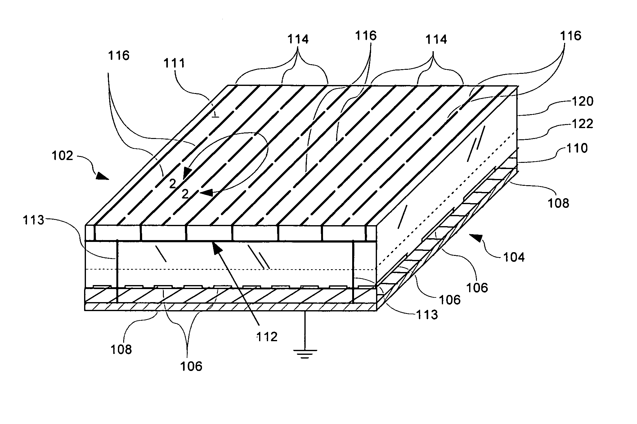
[0009] The invention concerns a radome that is at least partially formed of a dielectric substrate. Two or more conductive heating wires are disposed in or on the substrate. The conductive heating wires can be used for preventing ice buildup on the exterior of the radome during inclement weather. For example, an electric current can be caused to flow along a continuous length of one or more of the conductive heating wires to heat the radome. The conductive heating wires can also provide a degree of lightning protection for the radome and can reduce the buildup of static electricity. In this regard, the heating wires can be connected to a ground of a vehicle on which the radome is mounted.
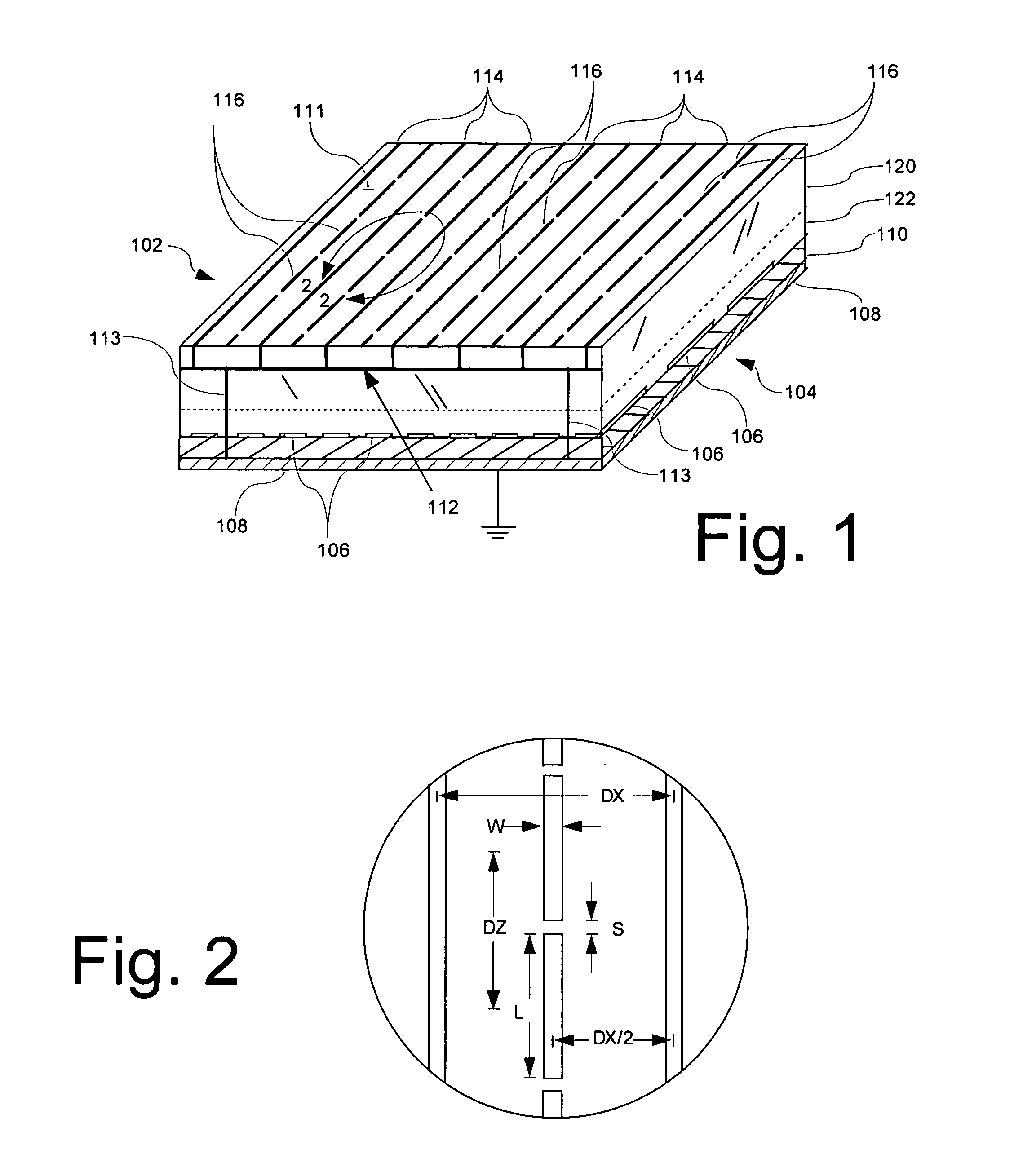
[0013] According to one embodiment, the capacitive elements can be positioned between adjacent ones of the heating wires. Further, if the capacitive elements are dipoles, then an elongated length of the dipoles can be aligned with an elongated length of the heating wires. For convenience of manufacture, the wires and / or the capacitive elements can be printed on a dielectric substrate forming a part of the radome. For example, the dielectric substrate can be selected to include one or more layers of a polyimide material disposed over a reinforced thermoset material. Further, the heating wires can be electrically connected to a ground of a vehicle on which the radome is mounted to improve lighting protection and anti-static protection of the radome.

Problems solved by technology

The conductive heating wires have an inductive reactance that can negatively interfere with the RF performance of the radome.

Method used


Image

  • Radome with detuned elements and continuous wires
  • Radome with detuned elements and continuous wires
  • Radome with detuned elements and continuous wires

Examples


Embodiment Construction

[0025]FIG. 1 is a perspective view of a portion of a radome 102 that covers or encloses an antenna system 104. The radome 102 in FIG. 1 is shown generally adjacent to the antenna system 104 in FIG. 1. However, it should be understood that the invention is not limited in this regard. Other radome arrangements are also possible in which the radome is spaced to a greater degree from the antenna system 104. For example, the radome 102 can be part of a dome structure that is constructed around an antenna that comprises a rotatable array. A wide variety of radome structures are well known in the art and all such radome structures are intended to be included within the scope of the invention without limitation. Accordingly, it should be understood that the method and construction of a radome described herein can be used in any type of radome.

[0026] Referring again to FIG. 1, the radome 102 can be at least partially comprised of a dielectric substrate 120. The dielectric substrate 120 can ...


PUM


Abstract

A radome uses traditional continuous heating wires mixed with detuned dipoles between heating wires and can be placed at any chosen distance from an array antenna or FSS. The continuous heating wires add a reactive component to the incident field phase, which is effectively cancelled out by the detuned dipoles which provide a capacitive component. The orthogonal components of the incident field are transmitted with very small losses over a wide number of scan angles. These heating and detuned dipoles can be printed on low loss dielectric materials. In addition, the printed elements of this radome can be scaled to operate over a chosen frequency band.

Description

STATEMENT REGARDING FEDERALLY SPONSORED RESEARCH OR DEVELOPMENT [0001] This invention was made with government support under Contract No. N00024-02-C-2302. The government has certain rights in the invention.BACKGROUND OF THE INVENTION [0002] 1. Statement of the Technical Field [0003] The inventive arrangements relate to radomes, and more particularly to environmental protection systems for radome. [0004] 2. Description of the Related Art [0005] Radomes are designed to protect enclosed electromagnetic devices, such as antennas, from environmental conditions such as wind, lightning, solar loading, ice, and snow. Conventional radome types include sandwich, space frame, solid laminate, and air supported. Radome induced wave perturbations are a principal consideration in radome construction. An ideal broad band radome is electromagnetically transparent to a large or selected number of radio frequencies, through a wide range of incident angles. However, in practice, conventional radomes a...

Claims


Application Information

Patent Timeline
IPC IPC(8): H01Q1/42
CPCH01Q1/425H01Q1/421
Inventor MUNK, BENEDIKT A.DELGADO, HERIBERTO JOSETAYLOR, ROBERT
Owner HARRIS CORP
Learn More