
Incident light source lens cone device for multi-wavelength time-resolved fluorescence measurement device

A technology of time-resolved fluorescence and measurement devices, which is applied in the field of medical optics applications, can solve problems such as poor accuracy and differences in transmitted light transmittance, and achieve the effects of simple and compact structure, good stability, and improved light protection

Pending Publication Date: 2021-04-13
SUZHOU INST OF BIOMEDICAL ENG & TECH CHINESE ACADEMY OF SCI
View PDF8 Cites 1 Cited by
  • Summary
  • Abstract
  • Description
  • Claims
  • Application Information

AI Technical Summary

Problems solved by technology

Therefore, no-clean immunoassay technology has been a research hotspot in the past 20 to 30 years. Siemens, Beckman and other companies have relevant technical reserves. The domestic company Beijing Kemei Biological Co., Ltd. has launched a series of high-throughput products based on Siemens’ patented photochemiluminescence technology. Immunoassay system, for the first time, realizes the clinical application of no-cleaning detection. The problem with this technology is that there is a large difference in the transmittance of emitted light in different samples, and the accuracy is poor when detecting hemolysis and hyperlipidemia samples.
[0006] For the time-resolved energy transfer technology, an optical entrance lens tube with good light resistance and high integration is required. At present, the optical lens tube is mostly a split structure, which is mostly used for laboratory research, and is not suitable for multi-wavelength time-resolved fluorescence measurement devices.

Method used


Image

  • Incident light source lens cone device for multi-wavelength time-resolved fluorescence measurement device
  • Incident light source lens cone device for multi-wavelength time-resolved fluorescence measurement device
  • Incident light source lens cone device for multi-wavelength time-resolved fluorescence measurement device

Examples


Embodiment Construction

[0016] The present invention will be further introduced below with reference to the accompanying drawings and specific embodiments.

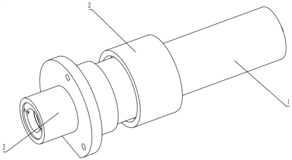
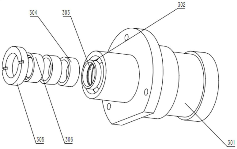
[0017] combine figure 1 , an incident light source lens barrel device for a multi-wavelength time-resolved fluorescence measurement device of the present invention is composed of three parts: a xenon lamp light source assembly 1, a xenon lamp gland 2, and an incident light path assembly 3, and the incident light path assembly 3 is a light source mirror The main body of the tube device, the xenon lamp assembly 1 is fixed on the light entrance assembly 3 by the xenon lamp gland 2 and the light entrance lens sleeve 301 through screw fitting, forming the light source lens barrel device for the multi-wavelength time-resolved fluorescence measurement device.

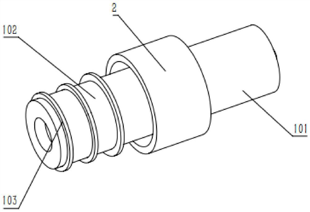
[0018] combine figure 2 , the xenon lamp assembly 1 includes a xenon lamp holder 101, a xenon lamp holder 102 and a xenon lamp adjustment pad 103, the xenon lamp holder 102 is inserted into th...


PUM


Abstract

The invention discloses an incident light source lens cone device for a multi-wavelength time-resolved fluorescence measurement device, and belongs to the field of application of medical optics in the IVD (in vitro diagnostic) medical equipment technology. The incident light source lens cone device consists of a xenon lamp light source component, a xenon lamp gland and an incident light path component. The incident light path component is the main body of the light source lens cone device. The Xenon lamp light source component and the light path component are installed together through the xenon lamp gland to form the incident light source lens cone device for a multi-wavelength time-resolved fluorescence measurement device. The incident light source lens cone device has the advantages that compared with a common optical lens cone, an integrated lens jacket structure is adopted, and compared with a split type lens jacket, the light shielding performance of a light path can be better guaranteed, the structure is more compact, the distance between a light source and an optical element is adjustable, and stable incident light is provided for the multi-wavelength time-resolved fluorescence measurement device.

Description

technical field [0001] The invention belongs to the field of medical optics application in IVD in vitro diagnostic medical equipment technology, in particular to a light source lens barrel device used for a multi-wavelength time-resolved fluorescence measurement device. Background technique [0002] For more than half a century, the mainstream immunoassay technology has gone through the stages of radioimmunoassay, enzyme-linked immunoassay, chemiluminescence immunoassay, etc. Currently, the amount of radioimmunoassay is very small due to the radioactive problem, and the enzyme-linked immunoassay is gradually being used due to the long detection time. Instead, chemiluminescence immunoassay is the current mainstream immunoassay technique. In the field of emergency detection and other immediate detection, chemiluminescence is difficult to be widely used due to the complexity of technology and high cost. These demands have given birth to immediate detection immunoassay technolog...

Claims


Application Information

Patent Timeline
Patent Type & Authority Applications(China)
IPC IPC(8): G01N21/64G01N21/01
CPCG01N21/6408G01N21/645G01N21/01
Inventor 高广兴冯勇通
Owner SUZHOU INST OF BIOMEDICAL ENG & TECH CHINESE ACADEMY OF SCI
Learn More