LED lamp and heat-dissipating structure thereof

a technology of heat dissipation structure and led lamp, which is applied in the direction of point-like light sources, lighting and heating apparatus, light sources, etc., can solve the problems of greatly limited heat transfer amount, shortening the life of led in light-emitting modules, and inability to effectively and quickly transfer heat to the outside. , to achieve the effect of prolonging the life of leds

Inactive Publication Date: 2007-11-01
CHAUN CHOUNG TECH
View PDF5 Cites 254 Cited by
  • Summary
  • Abstract
  • Description
  • Claims
  • Application Information

AI Technical Summary

Benefits of technology

[0008] The present invention is to provide a heat-dissipating structure of a LED lamp, by which the LED can be continuously operated under a suitable working temperature and the life of the LED can thus be prolonged.

Problems solved by technology

Therefore, it is an important issue for those engaged in this art to provide a LED lamp that has a heat-dissipating structure and can be assembled and manufactured easily.
However, in practice, conventional LED lamps still have the following disadvantages.
Since the heat-dissipating module of the LED lamp aims to transfer and dissipate the heat generated in the front of the light-emitting module, the heat generated in the back of the light-emitting module cannot be effectively and quickly transferred to the outside.
The amount of heat to be transferred is greatly limited, so that a relatively great amount of heat is accumulated in the back of the light-emitting module, causing the shortening of the life of the LED in the light-emitting module and the rapid aging and damage of the peripheral components.
Further, the sealed chamber is formed by assembling the heat-dissipating module and a lamp cover, so that the manufacturing procedure of the sealing connection is very complicated.

Method used


Image

  • LED lamp and heat-dissipating structure thereof
  • LED lamp and heat-dissipating structure thereof
  • LED lamp and heat-dissipating structure thereof

Examples


Embodiment Construction

[0021] The detailed description and the technical contents of the present invention will be explained with reference to the accompanying drawings. However, it should be understood that the drawings are illustrative but not used to limit the scope of the present invention.

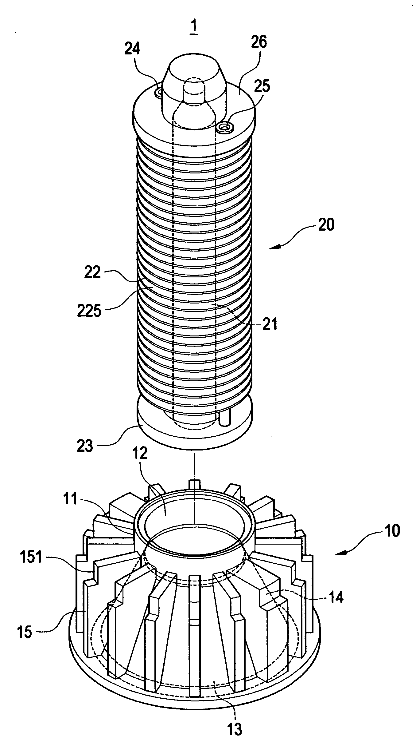
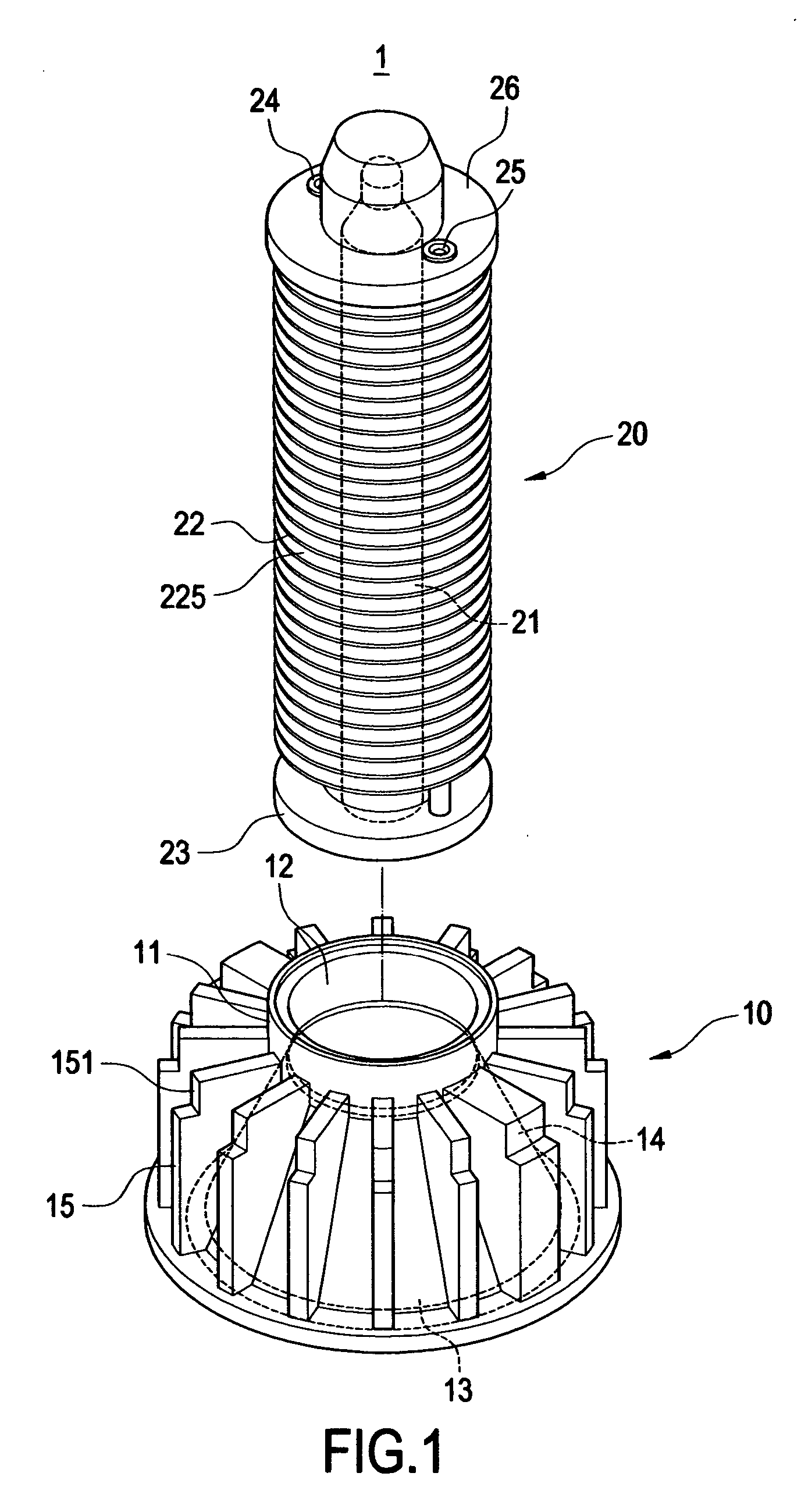
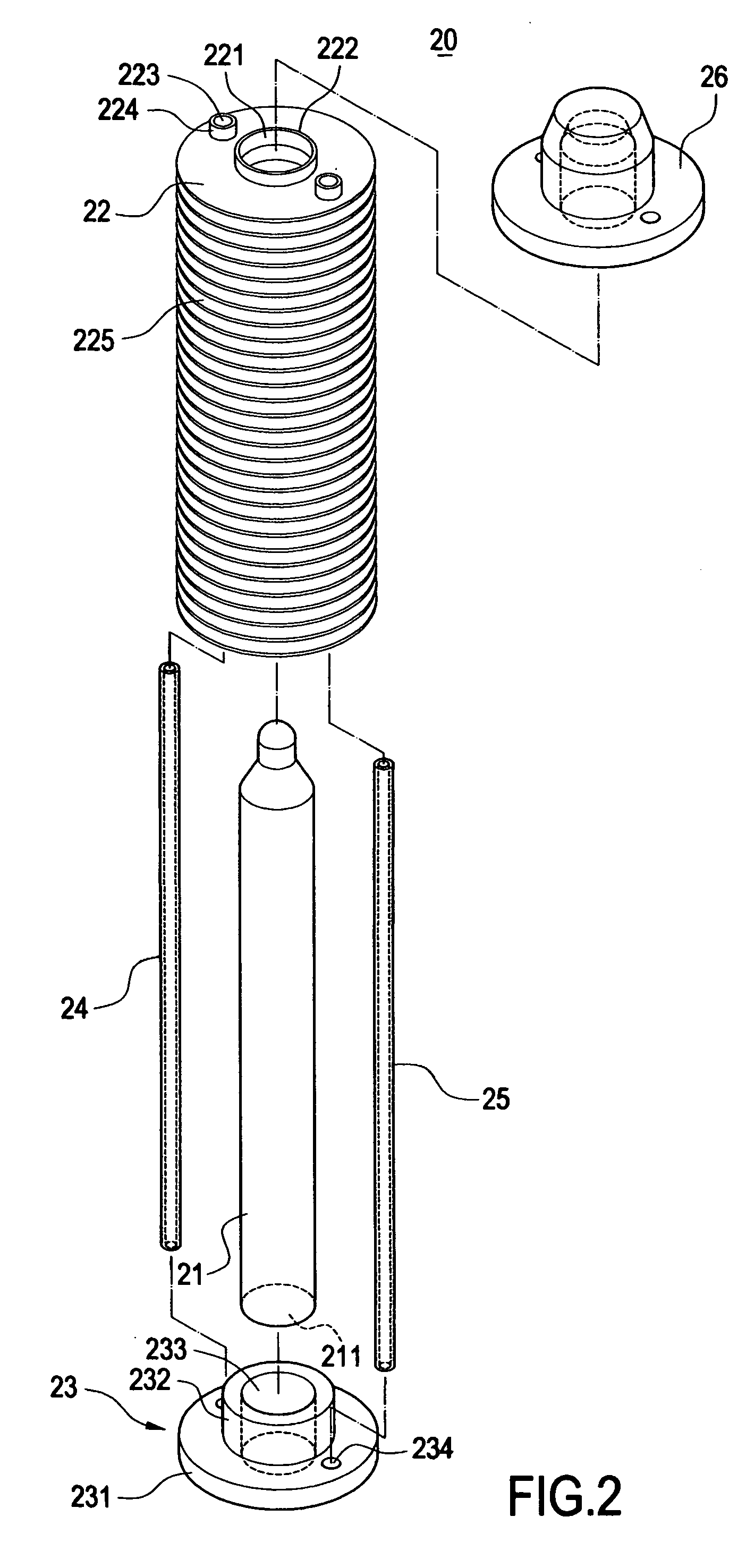
[0022] With reference to FIGS. 1 and 2, FIG. 1 is an exploded perspective view of the first and second heat-dissipating body of the present invention, and FIG. 2 is an exploded perspective view of the second heat-dissipating body of the present invention. The present invention provides a LED lamp and the heat-dissipating structure thereof. The LED lamp mainly comprises a heat-dissipating structure 1 and a lamp head assembly 5 (as shown in FIG. 3).

[0023] The heat-dissipating structure 1 comprises a first heat-dissipating body 10 and a second heat-dissipating body 20. The first heat-dissipating body 10 has a conical casing 11. The casing 11 can be made of suitable materials having excellent heat conductivity such as...


PUM


Abstract

The present invention is directed to a LED lamp and the heat-dissipating structure thereof. The heat-dissipating structure is used to dissipate the heat generated by the LED and comprises a first heat-dissipating body and a second heat-dissipating body. The first heat-dissipating body has a casing with an opening formed thereon. The second heat-dissipating body is connected on the first heat-dissipating body and comprises at least one heat pipe and a plurality of heat-dissipating fins connected to the heat pipe. With this arrangement, the LED continuously operates under a suitable working temperature and the life of the LED can thus be prolonged.

Description

BACKGROUND OF THE INVENTION [0001] 1. Field of the Invention [0002] The present invention relates to a LED lamp and a heat-dissipating structure thereof, and in particular to a LED lamp for illuminating and a heat-dissipating structure for transferring and dissipating the heat generated by the light emitting diode (LED). [0003] 2. Description of Prior Art [0004] Since the LED has many advantages such as high-illumination, energy-saving and long-life etc., it is widely applied to the illumination of the electronic devices or lamps. Further, in order to increase the illuminating region and the intensity of the light of the LED, a plurality of LEDs are usually assembled together to form a LED lamp. However, with the increase in the number of the assembled LEDs and the continuous developments of the high-power LEDs, the heat generated by such LEDs is gradually increasing accordingly. Therefore, it is an important issue for those engaged in this art to provide a LED lamp that has a heat-...

Claims


Application Information

Patent Timeline
Patent Type & Authority Applications(United States)
IPC IPC(8): F21V29/00
CPCF21V29/004F21Y2101/02F21V29/006F21K9/137F21V29/767F21V29/773F21V29/83F21V29/71F21V29/89F21K9/233F21Y2115/10F28D15/0275F21V29/51
Inventor WU, CHUNGHUANG, MENG-CHENGHSU, ZU-CHAO
Owner CHAUN CHOUNG TECH
Why Eureka
Try Eureka