Method and apparatus for cone beam CT dynamic imaging

Active Publication Date: 2007-11-01
UNIVERSITY OF ROCHESTER
View PDF19 Cites 25 Cited by
  • Summary
  • Abstract
  • Description
  • Claims
  • Application Information

AI Technical Summary

Benefits of technology

[0009] A new cone beam weighting scheme has been heuristically proposed for the FDK-based circular half scan reconstruction (FDKHSCW) to correct the density drop artifact to a certain degree along the rotation axis inherited with original FDK algorithm for large cone angle. Computer simulation on the Shepp-Logan phantom with and without noise showed an improvement when using the FDKHSCW over FDKFS and FDKHSFW in terms of the attenuation coefficient drop when the cone angle is large while maintaining the same visual image quality. FDKHSCW needs additional cone-beam weighting before filtering and only uses a scanning range of [β,180+β+2Δ], where β is the starting projection angle of the x-ray, and Δ is half of the full fan angle; both of them are defined in the scanning plane. As soon as the starting angle is determined, each projection image can be processed (cone-beam weighting for half scan, pixel weighting inherited by FDK, and filtering). So, it will take less time to reconstruct an object in comparison to the full scan scheme, a very desirable feature in practice. Here the half scan is defined as 180° plus cone angle of the scan geometry. In addition, the half-scan scheme provides a flexibility to choose any starting point for reconstruction as long as the scanning range is guaranteed, another preferable feature for cone beam CT dynamic imaging. If a full circle scan is performed, to increase temporal resolution of the system and cone beam CT reconstruction, a multiple of half scan reconstructions can be performed from the full circle scan by choosing the different starting point. Therefore it is another objective of the invention that using the half scan algorithm to reconstruct a multiple of half scan reconstructions from a circle or multiple circle scan projection images of an object to increase temporal resolution for cone beam CT dynamic imaging scan.
[0010] Based on the idea proposed by Silver (M. D. Silver, “A method for includ

Problems solved by technology

However, the spatial resolution of the reconstructed images from GHS is inferior to that of FDKISFW because data interpolation is less involve

Method used


Image

  • Method and apparatus for cone beam CT dynamic imaging
  • Method and apparatus for cone beam CT dynamic imaging
  • Method and apparatus for cone beam CT dynamic imaging

Examples


Example

[0028] Preferred embodiments of the invention will be set forth in detail with reference to the drawings, in which like reference numerals refer to like elements or steps throughout.

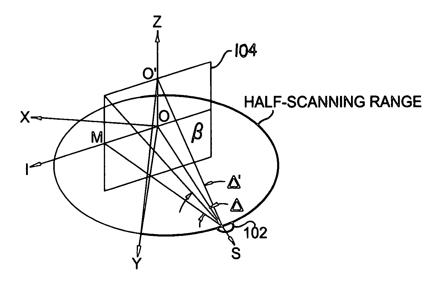
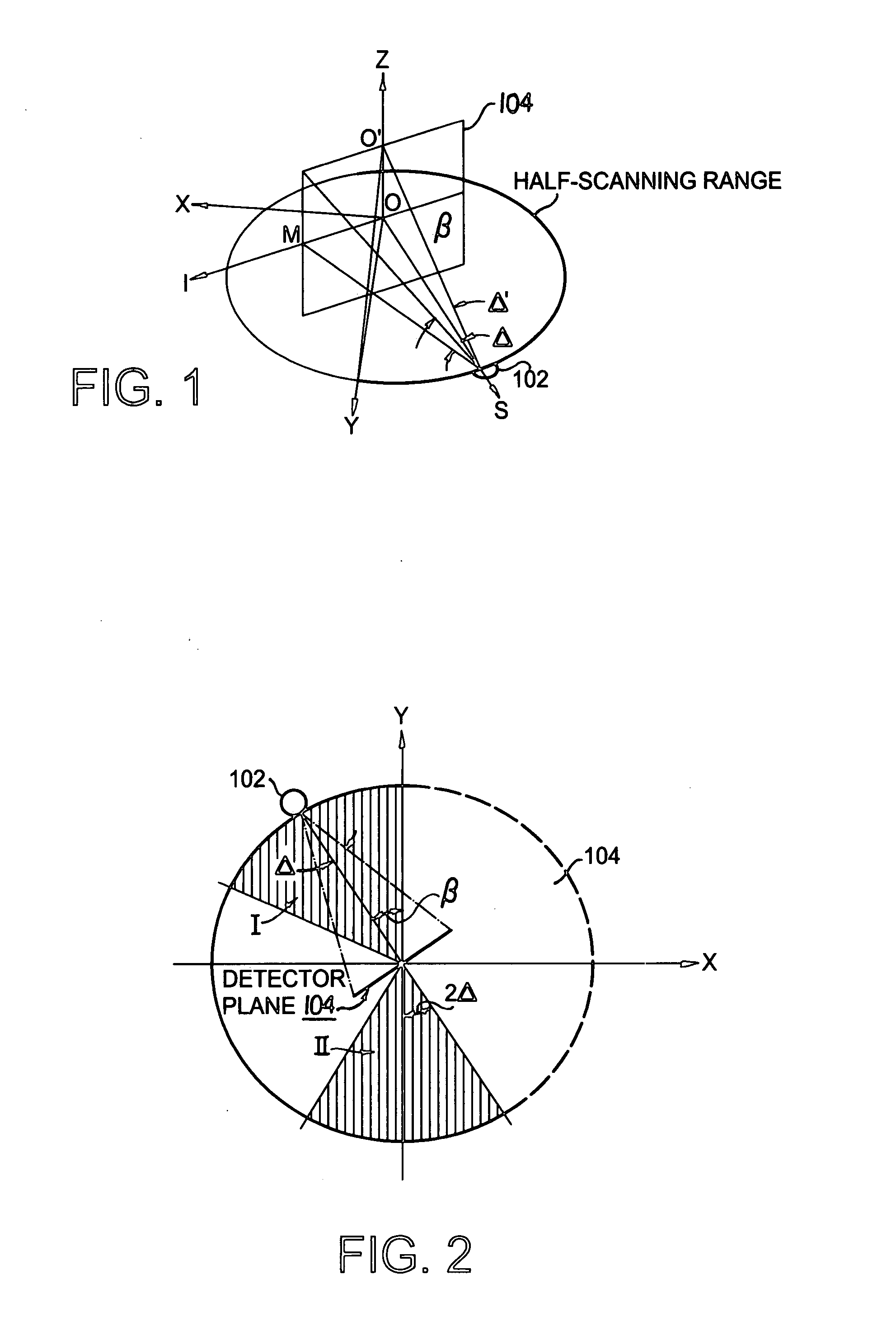
[0029] The FDK algorithm expands upon the fan beam algorithm by summing the contribution to the object of all the tilted fan beams. The reconstruction is based on filtering and back projecting a single fan beam within the cone. Based on the cone beam geometry in FIG. 1, which shows the relative locations of the cone beam emitter or other x-ray source 102 and the plane of the flat-panel detector 104, the formula of the FDK is: f⁡(x,y,z)=12⁢∫02⁢π⁢so2(so-s)2·{[Rβ⁡(np,m⁢ ⁢ξ)⁢soso2+m2⁢ξ2+n2⁢p2]*h⁡(np)}⁢ⅆβ⁢⁢s=-x⁢ ⁢sin⁢ ⁢β+y⁢ ⁢cos⁢ ⁢β;(1)

[0030] The * sign denotes the convolution; so: the distance from the x-ray source to the origin; n,m: integer value where n=0 and m=0 corresponds to the central ray passing through the origin; β: the projection angle defined in the scanning plane; p: the virtual detector samp...


PUM


Abstract

A cone-beam scanning system scans along a half circle. The reconstruction uses a weighting function which decreases for rows farther from the scan plane to take the redundancy of the projection data into account. Another embodiment uses a circle plus sparse helical scan geometry. Image data can be taken in real time.

Description

REFERENCE TO RELATED APPLICATION [0001] The present application claims the benefit of U.S. Provisional Patent Application No. 60 / 776,666, filed Feb. 27, 2006, whose disclosure is hereby incorporated by reference in its entirety into the present disclosure.STATEMENT OF GOVERNMENT INTEREST [0002] The work leading up to the present invention was supported by NIH Grants 8 R01 EB002775, R01 9 HL078181, and 4 R33 CA94300. The government has certain rights in the invention.FIELD OF THE INVENTION [0003] The present invention is directed to imaging and more specifically to a half-scan imaging technique using a weighting function to increase temporal resolution. DESCRIPTION OF RELATED ART [0004] The use of the half-scan method in cone beam CT has been a hot topic in recent years owing to the resultant improvement in temporal resolution. There are currently several different types of cone beam half-scan schemes, such as FDK-based, cone beam filtered-backprojection-based (CBFBP), and Grangeat-b...

Claims


Application Information

Patent Timeline
IPC IPC(8): G01N23/00
CPCA61B6/032A61B6/0435Y10S378/901G06T11/006A61B6/027A61B6/502
Inventor NING, RUOLAYANG, DONG
Owner UNIVERSITY OF ROCHESTER
Why Eureka
Try Eureka