
Detent apparatus for water temperature regulation of induction faucets

Inactive Publication Date: 2007-11-08
CHEN JAN SUN
View PDF6 Cites 9 Cited by
  • Summary
  • Abstract
  • Description
  • Claims
  • Application Information

AI Technical Summary

Benefits of technology

[0007] Therefore the primary object of the present invention is to solve the disadvantages of the conventional induction faucets mentioned above. The present invention provides a simpler detent apparatus for water temperature regulation of induction faucets. It is coupled with a water discharge means and can be operated steadier and fabricated and maintained easier.
[0009] By means of the detent apparatus set forth above, the detent portion can be directly formed on the mixer body to provide a firmed positioning and harnessing function without breaking down easily. The structure is formed in an integrated manner, thus is easier to fabricate and costs less. It overcomes the problems occurred to the conventional water temperature regulating means of induction faucets such as complex mechanism and difficult to fabricate and maintain.

Problems solved by technology

However, such a feature also makes control of water temperature by mixing cold and hot water more difficult than the conventional faucets.
Moreover, once the regulating water temperature is set, it is fixed and cannot be altered or fine-tuned by users to meet onsite requirements.
However, the temperature regulation mechanism takes a lot of space in the faucet.
As the conventional manual faucet does not have sufficient space to accommodate the automatic water temperature regulation mechanism, it requires a special design to do installation, such as including a detent means to limit swiveling of the handle on two ends to regulate the cold and hot water.
Such a design involves a more complex mechanism and incurs a higher cost.
Repairs and maintenance also are more difficult.

Method used


Image

  • Detent apparatus for water temperature regulation of induction faucets
  • Detent apparatus for water temperature regulation of induction faucets
  • Detent apparatus for water temperature regulation of induction faucets

Examples


Embodiment Construction

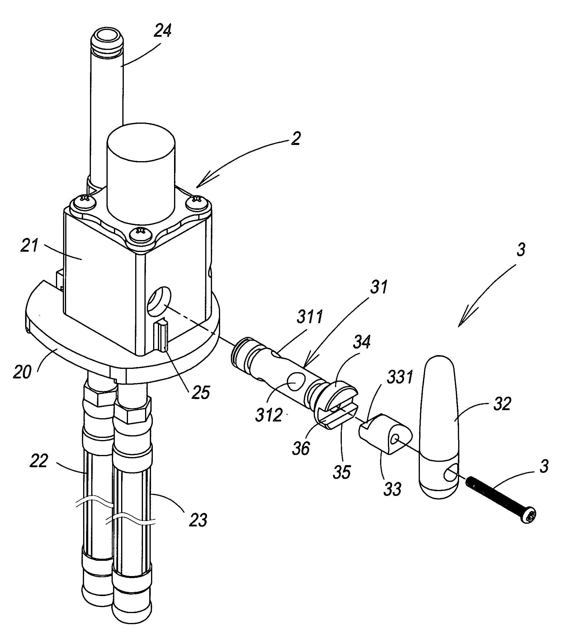
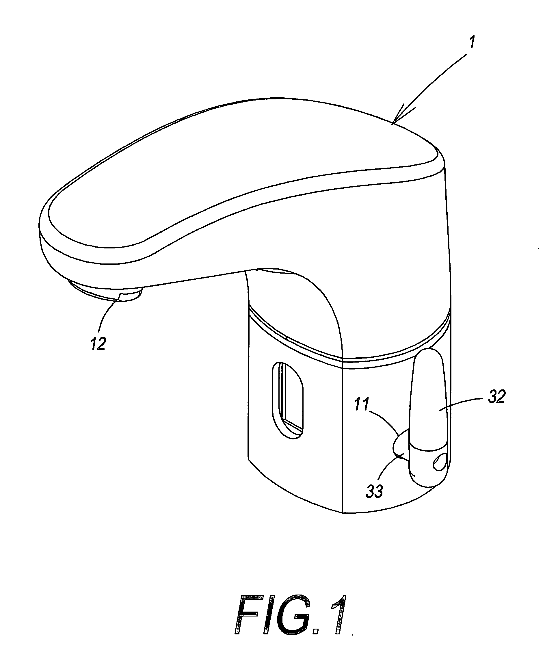
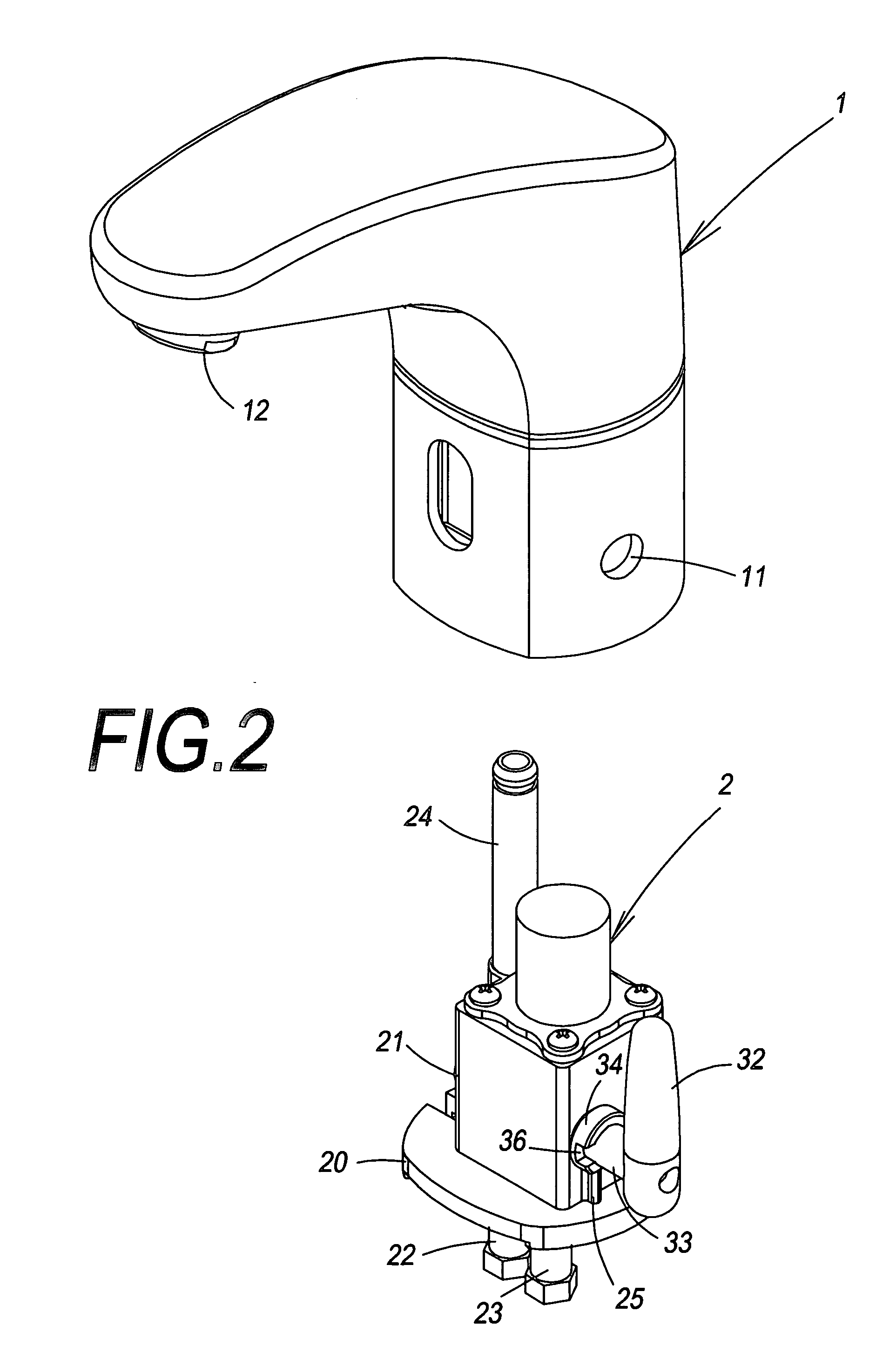
[0015] Referring to FIGS. 1, 2 and 3, the detent apparatus for water temperature regulation of induction faucets of the invention includes a faucet duct 1, a mixer 2 and a swiveling mechanism 3 located in the faucet duct 1 to regulate discharge water temperature according to individual user's requirement.

[0016] The faucet duct 1 is one spout type containing an induction control mechanism. It detects users and automatically discharges water through an electromagnetic switch (not shown in the drawings). The faucet duct 1 has a body with an aperture 11 formed on the surface to be coupled with a handle 32 of the swiveling mechanism 3 such that the handle 32 is located outside the faucet duct 1 to be operated by user's hands.

[0017] The mixer 2 has a body 21 and a base 20 that are coupled together. It is located in the faucet duct 1 and coupled with a cold water intake duct 22 and a hot water intake duct 23 that are functioned cooperatively with the swiveling mechanism 3 to control wate...


PUM


Abstract

A detent apparatus for water temperature regulation of induction faucets includes a mixer located in a faucet and a swiveling mechanism located in the mixer. The swiveling mechanism has a rotary valve and a handle located outside the mixer and the faucet. The handle is fastened to an end seat located on one end of the rotary valve through a coupling member. The detent apparatus includes a detent portion preferably formed integrally with the mixer and located on the outer surface of the mixer body in a protrusive manner. The detent portion has a top end surface spaced beneath a bucking portion of the end seat at a selected distance. When the end seat is swiveled the bucking portion hits a left bucking angle or a right bucking angle of the top end surface thereby the swiveling angle of the end seat is confined within a limited range.

Description

BACKGROUND OF THE INVENTION [0001] 1. Field of the Invention [0002] The present invention relates to a detent apparatus for water temperature regulation of induction faucets and particularly to an apparatus for induction faucets to manually adjust water discharge temperature that has two detent limits to confine swiveling of a water temperature regulation means and can be formed easily. [0003] 2. Description of the Prior Art [0004] The water discharge controllers of automatic induction faucets now available on the market commonly adopt a magnetic switch (solenoid valve) to control water discharge and amount by automatically detecting the presence of users without touching or depressing a handle. Such types of faucets are more sanitary and also can save water consumption. However, such a feature also makes control of water temperature by mixing cold and hot water more difficult than the conventional faucets. Hence they mostly aim to deliver cold water. [0005] On the other hand, in so...

Claims


Application Information

Patent Timeline
IPC IPC(8): G05D23/13
CPCE03C1/055Y10T137/86823
Inventor CHEN, JAN SUN
Owner CHEN JAN SUN
Learn More