Apparatus For Ultrasonic Vibration-Assisted Machining

a technology of vibration-assisted machining and equipment, which is applied in the direction of mechanical vibration separation, superfinishing machines, manufacturing tools, etc., can solve the problems of low cutting efficiency, not increasing the life of tools, and not improving surface finish, etc., and achieves the effect of reducing the vibration of the vibration horn

Inactive Publication Date: 2007-11-08
AGENCY FOR SCI TECH & RES
View PDF11 Cites 12 Cited by
  • Summary
  • Abstract
  • Description
  • Claims
  • Application Information

AI Technical Summary

Benefits of technology

[0009] According to a first aspect there is provided an apparatus for ultrasonic vibration-assisted machining, the apparatus comprising: an ultrasonic transducer for generating ultrasonic waves in a vibration horn; a first clamp on the vibration horn at a static node of the ultrasonic waves; and a second clamp between the first clamp and a lowermost end of the vibration horn. The second clamp comprises a linear bearing for reducing vibration of the vibration horn in a direction laterally of the vibration horn, and allowing vibration of the vibration horn in the direction of a longitudinal axial of the vibration horn.
[0012] The second clamp may comprise a linear bearing for reducing vibrations of the vibration horn in a direction laterally of the vibration horn and allowing vibration of the vibration horn in the direction -of a longitudinal axis of the vibration horn.

Problems solved by technology

The expected advantages have not been realized, however, as it did not increase tool life nor improve surface finish.
Also, cutting efficiency is low as the cutting speed must be less than the vibration speed.
However, a diamond tool bit cannot be used on steel due to the strong chemical reaction between the diamond and the steel.
Furthermore, the operational temperature of the device increases due to the larger power, and is easily damaged due to the higher temperature.
Also, lateral (or radial) vibration damages the tool bit.
It also causes deeper cuts and therefore lower quality surface finish.
However such methods have many disadvantages.
Also, they are not capable of manufacturing moulds with high durability as the nickel tends to lift off the steel workpiece.

Method used


Image

  • Apparatus For Ultrasonic Vibration-Assisted Machining
  • Apparatus For Ultrasonic Vibration-Assisted Machining
  • Apparatus For Ultrasonic Vibration-Assisted Machining

Examples


Embodiment Construction

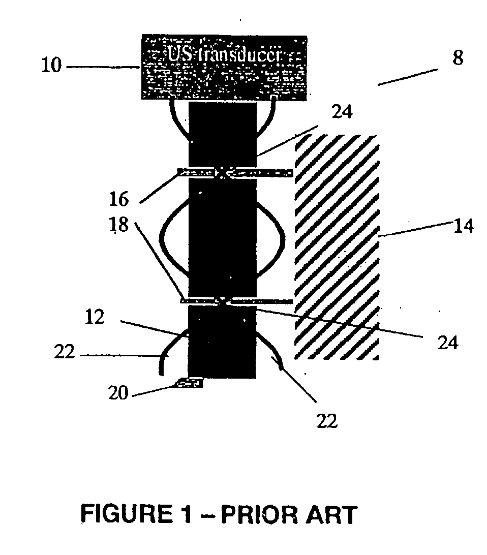
[0021] To refer to FIG. 1, there is shown a prior art apparatus 8. Here, there is an ultrasound transducer 10 with a vibration horn 12. These are mounted to a mounting block 14 by upper clamp 16 and lower clamp 18. The tool bit 20 is at the lowermost end of the vibration horn 12. The ultrasound transducer 10 produces sound waves 22 at, for example, 40 KHz. The waves have maximum amplitude at ultrasound transducer 10, and at tool bit 20 to maximize the movement of tool bit 20. To hold the vibration horn 12 in place, and to prevent unwanted radial (or lateral) movement, the vibration horn 12 is secured to mounting block 14 by upper clamp 16 and lower clamp 18. Clamps 16, 18 are located at static node points 24 to allow them to function without interfering with the operation of tool bit 20. However, that means there is inherently a gap between lower clamp 18 and tool bit 20. This allows unwanted motion to occur at tool bit 20, the unwanted vibration being induced by vibration horn 12. ...


PUM

PropertyMeasurementUnit
diameteraaaaaaaaaa
diameteraaaaaaaaaa
wavelengthaaaaaaaaaa

Abstract

Apparatus for ultrasonic vibration-assisted machining, the apparatus comprising an ultrasonic transducer for generating ultrasonic waves in a vibration horn; first clamp on the vibration horn at a static node of the ultrasonic waves; and a second clamp between the first clamp and a lowermost end of the vibration horn. The second clamp comprises a linear bearing for reducing vibration of the vibration horn in a direction laterally of the vibration horn, and allowing vibration of the vibration horn in the direction of a longitudinal axial of the vibration horn.

Description

FIELD OF THE INVENTION [0001] This invention relates to apparatus for ultrasonic vibrations-assisted machining and refers particularly, though not exclusively to apparatus for ultrasonic vibration-assisted machining of metals such as steel and stainless steel. BACKGROUND OF THE INVENTION [0002] Ultrasonic vibration-assisted machining has several important advantages. One important advantage flows from the friction reducing action, which arises when the cutting edge or point of the tool separates from the work during each vibration cycle and which introduces an ultrasonic pumping action. This pumping action allows transmission of cooling fluids to all areas of the workpieace area. The cooling fluid may be air. [0003] Normal machining has an accuracy of greater than 5 μm and uses ordinary machine tools. Ultrasonic vibration-assisted machining was introduced in the 1960s to provide advantages over normal machining. The expected advantages have not been realized, however, as it did not ...

Claims


Application Information

Patent Timeline
Patent Type & Authority Applications(United States)
IPC IPC(8): B24B1/04B23B37/00
CPCB06B3/00B23B29/125B23B37/00B23B2226/31B24B35/00B23P25/00B24B1/04B24B13/015B23B2270/10
Inventor LIU, XIANG DONGDING, XIN
Owner AGENCY FOR SCI TECH & RES
Why Eureka
Try Eureka