Supercharge Your Innovation With Domain-Expert AI Agents!

Logic circuit system and method of changing operating voltage of a programmable logic circuit

a logic circuit and operating voltage technology, applied in the direction of power consumption reduction, pulse technique, instruments, etc., can solve the problems of over-consuming electric power and reducing the upper limit of the operable clock frequency, and achieve the effect of reducing power consumption

Inactive Publication Date: 2007-11-08
KK TOSHIBA
View PDF10 Cites 0 Cited by
  • Summary
  • Abstract
  • Description
  • Claims
  • Application Information

AI Technical Summary

Benefits of technology

The invention provides a logic circuit system that can automatically adjust clock frequency and operating voltage based on the processing capabilities of a programmable logic circuit, reducing power consumption. The system includes a programmable logic circuit, a circuit configuration information supplier, a change controller, an operation time measurer, and a clock-and-voltage supplier. The method involves measuring operation times for different unit circuits, calculating a new frequency for the clock signal, finding a new operating voltage needed for the programmable logic circuit, and changing the operating voltage and clock signal to the new settings. This results in improved performance and efficiency of the programmable logic circuit.

Problems solved by technology

Correspondingly, excess electric power is consumed, because the operating speed of the whole integrated circuit is set to be capable of performing the processing of the process step that requires the highest processing capability in spite of the fact that there are process steps requiring only low processing capability.
However, where the operating voltage is lowered, the upper limit of the operable clock frequency is reduced.

Method used


Image

  • Logic circuit system and method of changing operating voltage of a programmable logic circuit
  • Logic circuit system and method of changing operating voltage of a programmable logic circuit
  • Logic circuit system and method of changing operating voltage of a programmable logic circuit

Examples


first exemplary embodiment

of a Logic Circuit System

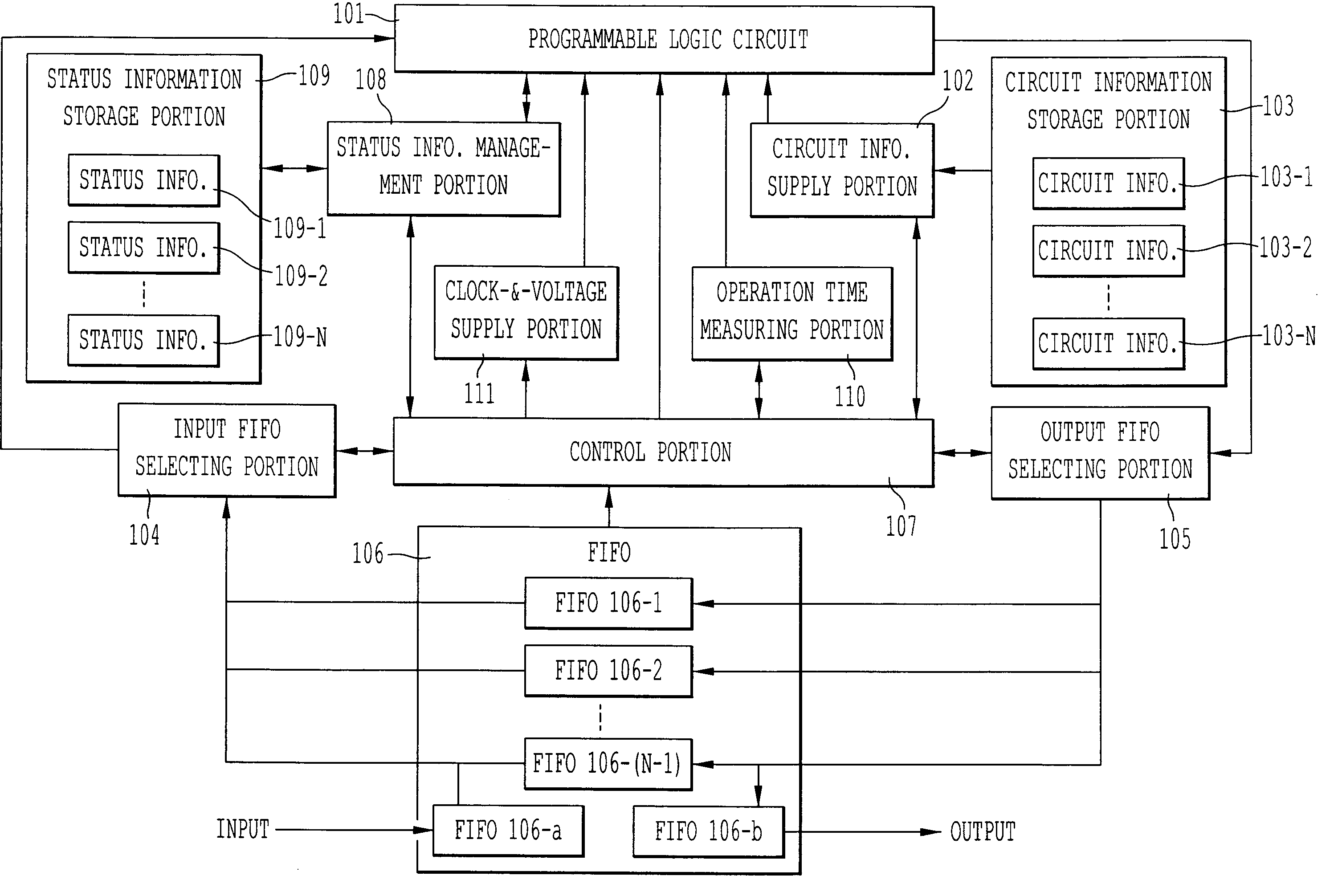
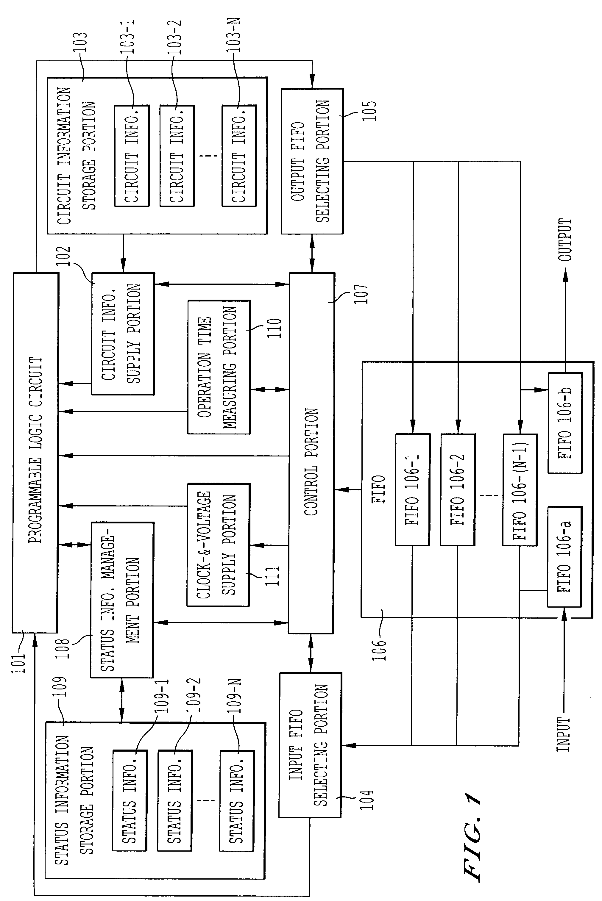
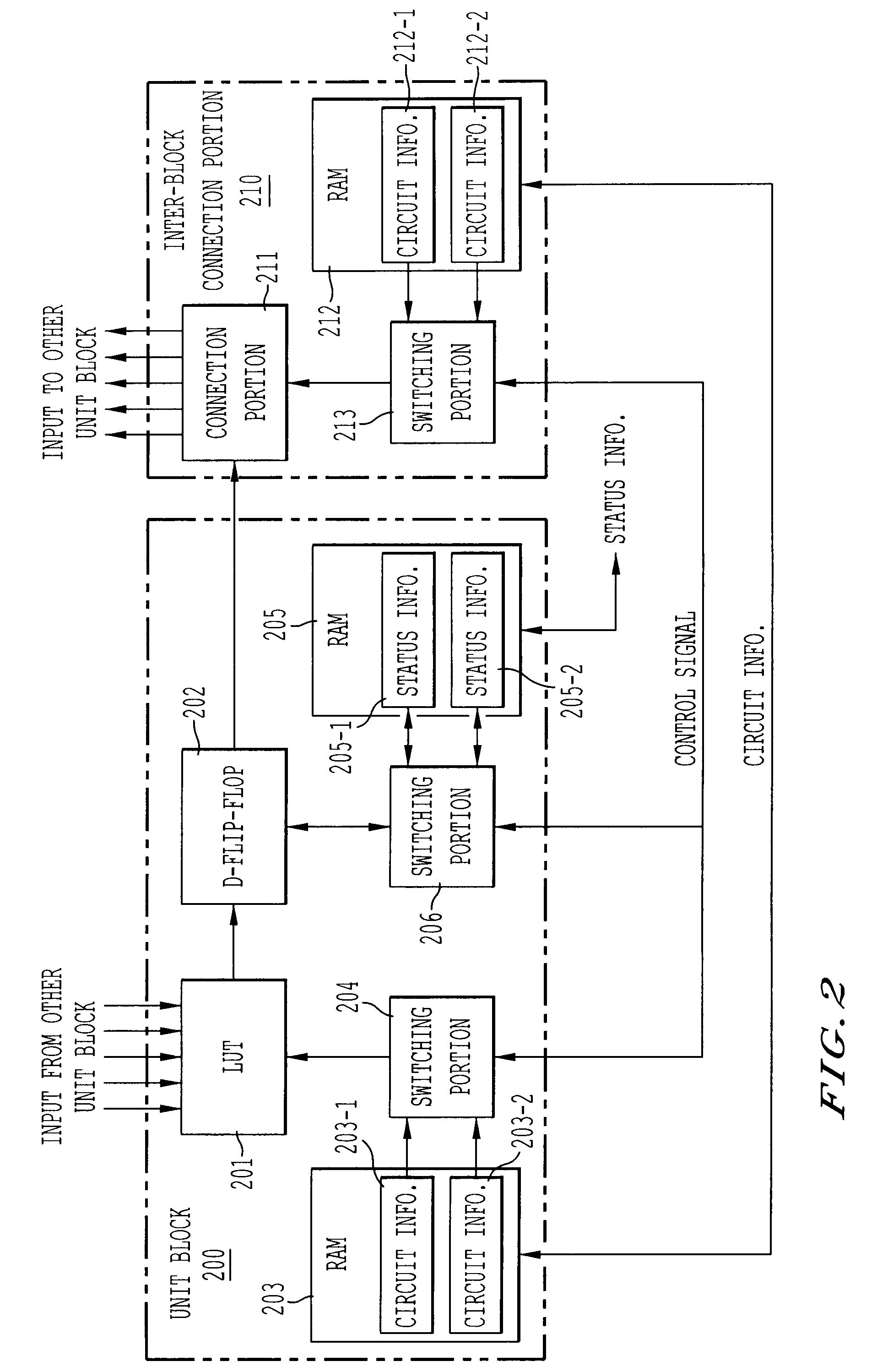
[0063]FIG. 1 shows a logic circuit system using a programmable logic circuit according to a first exemplary embodiment of the present invention. The logic circuit system of the present exemplary embodiment has a programmable logic circuit 101 including an assemblage of the unit blocks 200 of FIG. 2, a circuit information supply portion 102 for supplying circuit information from the outside to the programmable logic circuit 101, and a circuit information storage portion 103 for storing the circuit information.

[0064] The logic circuit system of the present exemplary embodiment has FIFOs 106 connecting the unit circuits realized by the programmable logic circuits 101, an input FIFO selecting portion 104 for selecting circuits which are connected with the input sides of the unit circuits realized by the programmable logic circuit 101 from the FIFOs 106, and an output FIFO selecting portion 105 for selecting circuits which are connected with the output sides of ...

second exemplary embodiment

of a Logic Circuit System

[0103] A logic circuit system of a second exemplary embodiment of the present invention is described below. The present exemplary embodiment differs with the first exemplary embodiment in the number of programmable logic circuits. In the present exemplary embodiment, there are plural programmable logic circuits. So the structure of a control portion 507 is different from that of the control portion 107 of the first exemplary embodiment. FIG. 5 shows the structure of the logic circuit system of the present exemplary embodiment.

[0104] The logic circuit system of the present exemplary embodiment can operate plural unit circuits at the same time. The control portion 507 determines an assignment of unit circuits to programmable logic circuits 101-1, 101-2, . . . , 101-m. Note that the initial values may be predetermined.

[0105] Where there are plural programmable logic circuits, the control of the clock frequency and operating voltage as described in the first e...

third exemplary embodiment

of a Logic Circuit System

[0130] A logic circuit system of a third exemplary embodiment of the present invention is described below with reference to FIG. 9. The logic circuit system of the present exemplary embodiment is identical in configuration with the second exemplary embodiment. The operation of the assignment control portion 703 is different.

[0131]FIG. 9 is a flowchart of processing performed by the assignment control portion 703 of the present exemplary embodiment to adjust the assignment of the unit circuits.

[0132] (Step 901)

[0133] The assignment control portion 703 finds the total operation time of each programmable logic circuit. The total operation time of each programmable logic circuit is found by totalizing the operation times of the unit circuits for each programmable logic circuit.

[0134] (Step 902)

[0135] The assignment control portion 703 finds the average of the total operation times of all the programmable logic circuits.

[0136] (Step 903)

[0137] The assignme...


PUM


Abstract

A logic circuit system with power consumption that is reduced by automatically varying the clock frequency and operating voltage according to processing capability imposed on programmable logic circuits. The programmable logic circuits are capable of achieving plural circuit functions dynamically and can change realized circuit functions during operation. In addition, the system has a voltage supply portion for supplying a voltage to the programmable logic circuits, a clock signal supply portion for supplying a clock signal to the programmable logic circuits, a change control portion for changing the circuit functions realized by the programmable logic circuits to any one of the circuit functions, an operation time measuring portion for measuring the operation times of the programmable logic circuits to perform processing to achieve the circuit functions, respectively, and a clock-and-voltage determination portion for determining the frequency of the clock signal and the voltage, using the operation times.

Description

CROSS-REFERENCE TO RELATED APPLICATIONS [0001] This application is a continuation application of Ser. No. 10 / 960,707, filed Oct. 8, 2004, which is based upon and claims the benefit of priority from Japanese Patent Applications No. 2003-349430, filed on Oct. 8, 2003, and No. 2004-228919, filed on Aug. 5, 2004, the entire contents of each of which are incorporated herein by reference.BACKGROUND OF THE INVENTION [0002] 1. Field of the Invention [0003] The present invention relates to a logic circuit system utilizing programmable logic circuits that can reconfigure their circuit configuration and change their circuit functions during operation. [0004] 2. Description of the Related Art [0005] Where a circuit performing processing consisting of plural process steps is made up of one integrated circuit, the processing capability of some portions of the integrated circuit are superfluous. Correspondingly, excess electric power is consumed, because the operating speed of the whole integrated...

Claims


Application Information

Patent Timeline
Patent Type & Authority Applications(United States)
IPC IPC(8): H03K19/173H01L21/822G06F1/26G06F1/32H01L21/82H01L27/04H03K19/00
CPCG06F1/3203G06F1/324G06F1/3243G06F1/3296H03K19/0008H03K19/0016Y02B60/1285H03K19/17752H03K19/17756H03K19/17784H03K19/17788Y02B60/1217Y02B60/1239H03K19/1736Y02D10/00
Inventor OONEDA, TAKUKANNO, SHINICHITARUI, MASAYAMIYAMOTO, YUKIMASA
Owner KK TOSHIBA
Features
  • R&D
  • Intellectual Property
  • Life Sciences
  • Materials
  • Tech Scout
  • Unparalleled Data Quality
  • Higher Quality Content
  • 60% Fewer Hallucinations
Learn More