Wireless picocellular RFID systems and methods

a picocellular and wireless technology, applied in the direction of near-field systems using receivers, instruments, burglar alarm mechanical actuation, etc., can solve the problems of poor signal strength, expensive implementation and maintenance, and conventional approach to rfid. equipment-intensive and labor-intensive problems

Inactive Publication Date: 2007-11-08
CORNING OPTICAL COMM LLC
View PDF77 Cites 119 Cited by
  • Summary
  • Abstract
  • Description
  • Claims
  • Application Information

AI Technical Summary

Problems solved by technology

Also, picocells allow for selective wireless coverage in small regions that otherwise would have poor signal strength when covered by larger cells created by conventional base stations.
This conventional approach to RFID is equipment-intensive and labor-intensive, and tends to be expensive to implement and maintain.

Method used


Image

  • Wireless picocellular RFID systems and methods
  • Wireless picocellular RFID systems and methods
  • Wireless picocellular RFID systems and methods

Examples


Embodiment Construction

[0022] Reference is now made in detail to the present preferred embodiments of the invention, examples of which are illustrated in the accompanying drawings. Whenever possible, the same or analogous reference numbers are used throughout the drawings to refer to the same or like parts.

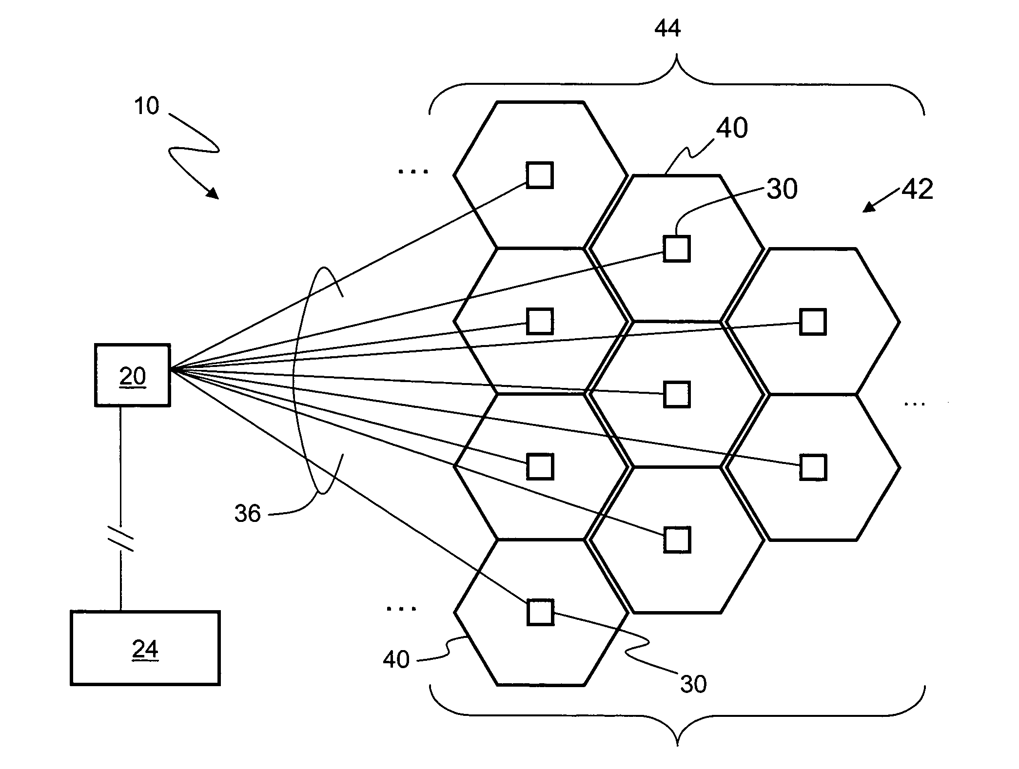
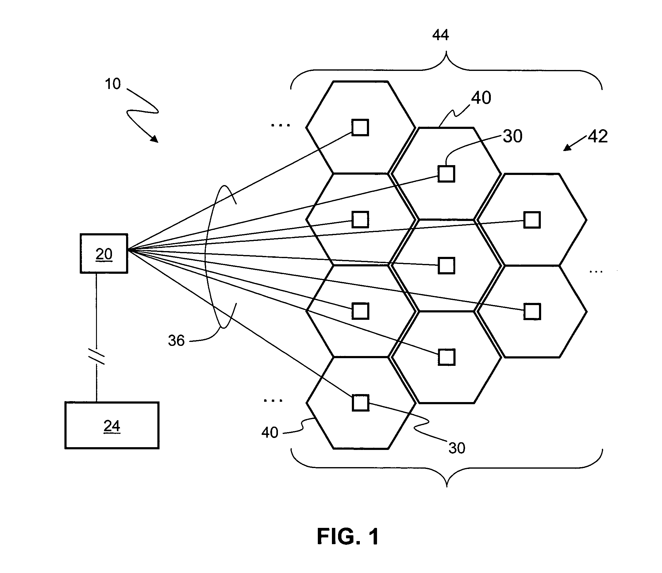
[0023]FIG. 1 is a schematic diagram of an example embodiment of a wireless picocellular RFID system 10 according to the present invention. System 10 includes a central control station 20 (also called a “head end”) where all the network management and signal processing is done, and where communication to outside networks such as outside network 24 is established. The central control station 20 is operably coupled to a number of electrical-optical (E-O) access point devices 30 via corresponding RF optical communication links 36 In a preferred embodiment, RF optical communication links 36 include optical fibers, e.g., downlink and uplink optical fibers, as discussed below. The E-O access point devices 30 ...


PUM


Abstract

The wireless radio-frequency identification (RFID) picocellular system includes a central control station optically coupled to one or more electrical-optical (E-O) access point devices that generate the individual picocells. The central control station includes service units that provide conventional wireless cellular services, and further includes one or more RFID reader units. The E-O access point devices are adapted to receive electromagnetic RFID tag signals from RFID tags within the associated picocell and transmit optical RFID tag signals to the central control station, which converts the optical RFID tag signals to electrical RFID tag signals, which are then received by the one or more RFID reader units. The system allows for large numbers of RFID tags in the picocellular coverage area to be quickly read and the information stored. The relatively small size of picocells allows for high-precision locating and position tracking of items without the need for manually scanning RFID tags with an RFID reader.

Description

BACKGROUND OF THE INVENTION [0001] 1. Field of the Invention [0002] The present invention relates generally to wireless communication systems, and particularly to wireless picocellular communication systems and radio-frequency identification (RFID) systems. [0003] 2. Technical Background [0004] Wireless communication is rapidly growing, with ever-increasing demands for high-speed mobile data communication. As an example, so-called “wireless fidelity” or “WiFi” systems and wireless local area networks (WLANs) are being deployed in many different types of areas (coffee shops, airports, libraries, etc.). Wireless communication systems communicate with wireless devices called “clients,” which must reside within the wireless range or “cell coverage area” in order to communicate with the access point device. Wireless Picocellular Systems [0005] One approach to deploying a wireless communication system involves the use of “picocells,” which are radio-frequency (RF) coverage areas having a...

Claims


Application Information

Patent Timeline
Patent Type & Authority Applications(United States)
IPC IPC(8): G08B13/14H04Q7/20G08B1/08G08B5/22H04W16/24H04W88/08
CPCG08B21/0275G08B21/0283H04W88/085H04B5/02H04W16/24H04B5/0062
Inventor EASTON, MARTYN N.SAUER, MICHAELVODHANEL, RICHARD S.
Owner CORNING OPTICAL COMM LLC
Why Eureka
Try Eureka