Tunable Arrangements

a microwave/millimeterwave and arrangement technology, applied in the direction of slot antennas, antenna details, antennas, etc., can solve the problems of large sized devices, high power consumption, high cost, etc., and achieve the effect of low cost, simple design, and low power consumption

Inactive Publication Date: 2007-11-08
HIGHBRIDGE PRINCIPAL STRATEGIES LLC AS COLLATERAL AGENT
View PDF12 Cites 18 Cited by
  • Summary
  • Abstract
  • Description
  • Claims
  • Application Information

AI Technical Summary

Benefits of technology

[0006] What is needed is therefore a tunable microwave arrangement comprising a tunable impedance surface which is small, cost-effective and which does not require a high power consumption. Still further an arrangement is needed which is adaptable or reconfigurable. Particularly an arrangement is needed which can be used as a beam scanning antenna or as a phase modulator, for example in microwave telecommunication systems. Still further an arrangement is needed which has a simple design. A beam scanning anten

Problems solved by technology

However, they are expensive, large sized devices which also require a high power consumption.
Also such antennas based on semiconductor technology are known, but they are quite expensive, large and require a high power consumption.
However, it is a drawback of this antenna that it needs extremely large DC voltages in order to be able to allows for beam scanning.
However, it does not address any tunable surface impedance or beam scan

Method used


Image

  • Tunable Arrangements
  • Tunable Arrangements
  • Tunable Arrangements

Examples


Embodiment Construction

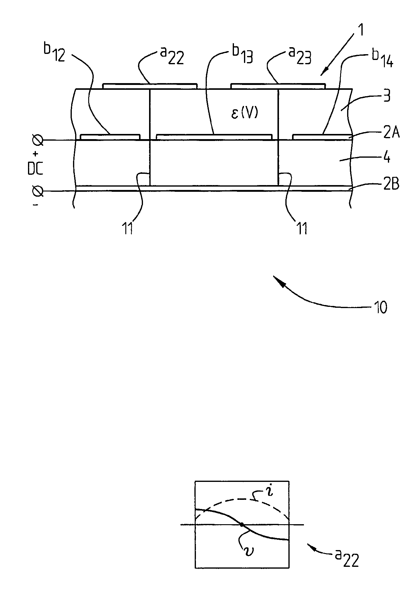
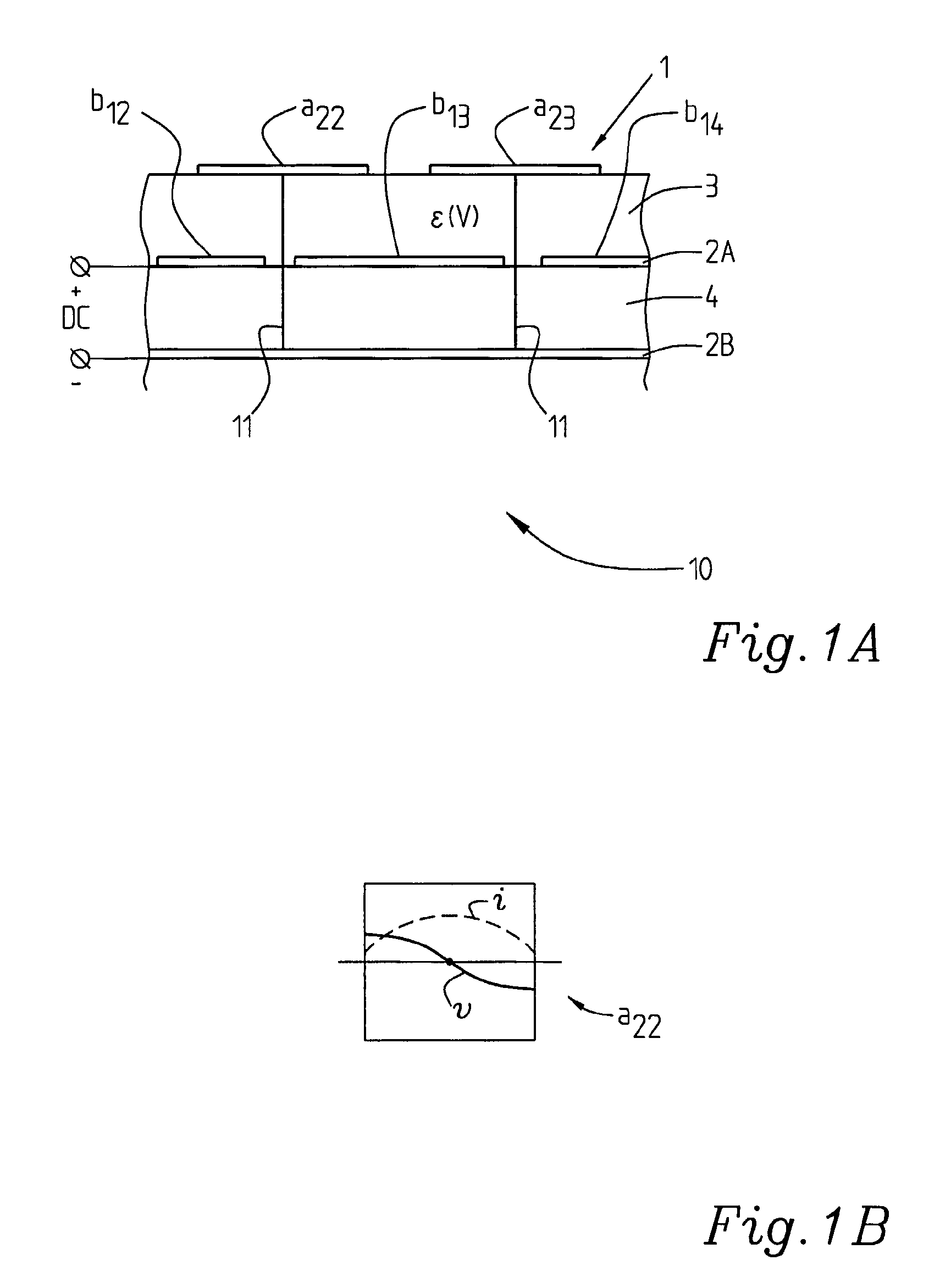
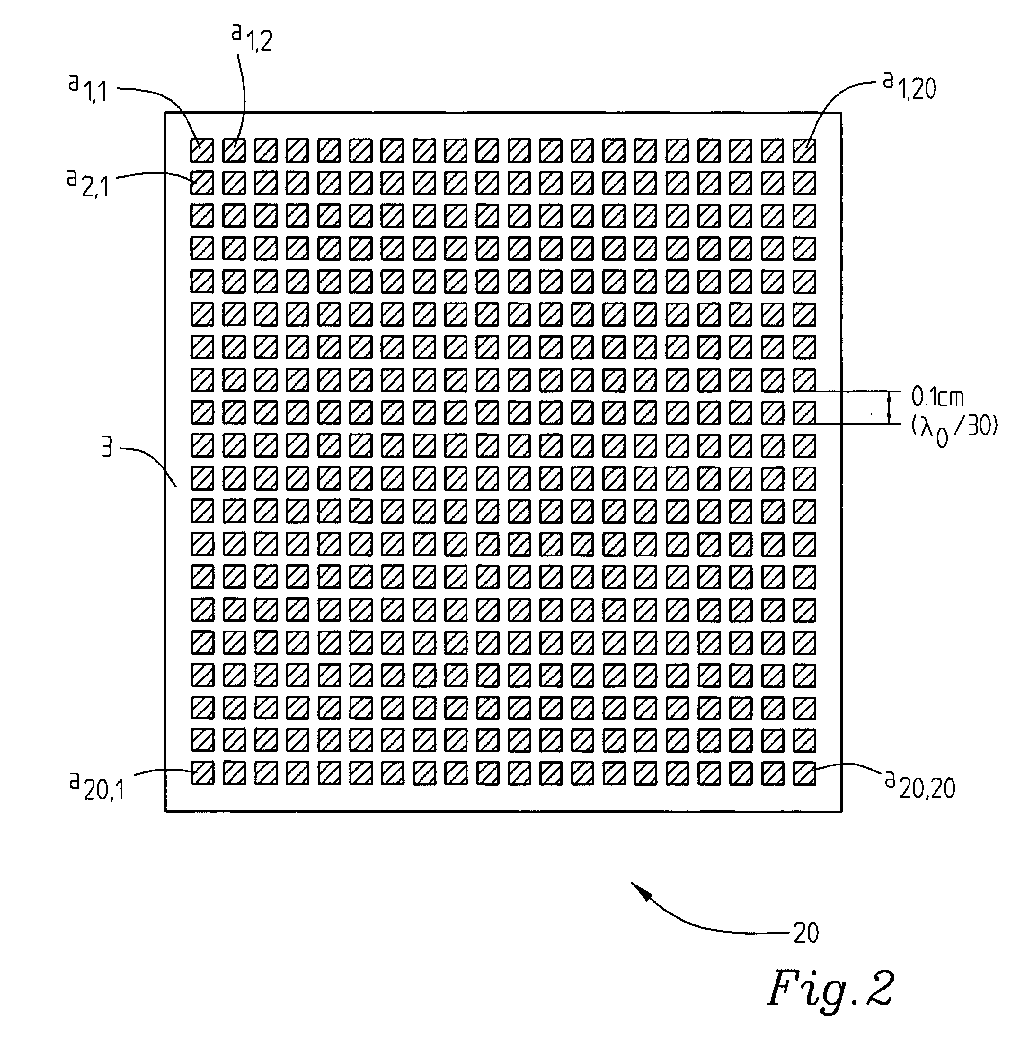
[0039]FIG. 1A shows a first embodiment of the invention comprising an arrangement in the form of a reflective radiator array 10. It comprises a first metal layer 1 comprising a number of radiators a22, a23, of which only these two radiators are illustrated since FIG. 1A only shows a fragment of the radiator array and it is shown in its entirety in FIG. 2.

[0040] Between the first metal layer 1 comprising the reflective radiators a22 , a23 and a second metal layer 2A which is patterned to form a split-up structure with openings, comprising, here, elements b12, b13, b14 which are so disposed that tiny openings are provided, a ferroelectric layer 3 is disposed. The ferroelectric layer comprises a high dielectric permittivity which is DC field dependent (ε(V)). The ferroelectric material may comprise a thin or a thick film layer, a ceramic etc. ε(V) may be between 225 and 200, although these values only are given for exemplifying reasons. As referred to above it may be lower as well as ...


PUM


Abstract

The present invention relates to a tunable microwave/millimeter-wave arrangement comprising a tunable impedance surface. It comprises an Electromagnetic Bandgap Structure (EBG) (Photonic Bandgap Structure) comprising at least one tunable ferroelectric layer (3), at least one first, top, metal layer (1) and at least one second metal layer (2A, 2B). Said first (1) and second metal layers (2A) are disposed on opposite sides of the/a ferroelectric layer (3), and at least the first, top, metal layer (1) is patterned and the dielectric permittivity of the at least one ferroelectric layer (3) is dependent on a DC biasing voltage directly or indirectly applied to first (1) and/or second (2A, 2B) metal layers disposed on different sides of the/a ferroelectric layer.

Description

FIELD OF THE INVENTION [0001] The present invention relates to a tunable microwave / millimeter-wave arrangement comprising a tunable impedance surface. Particularly the invention relates to such an arrangement comprising a beam scanning antenna or a frequency selective surface or a phase modulator. Even more particularly the invention relates to such an arrangement comprising a reflection and / or a transmission type antenna. STATE OF THE ART [0002] It has been realised that in some microwave systems of different kinds, for example microwave telecommunication systems, tunable arrangements which comprise a tunable impedance surface are required. Particularly it has been realised that arrangements having a small size and being adaptable or reconfigurable are needed. It has also been realised that for example beam scanning antennas or phase modulators are needed which are small sized, adaptable or reconfigurable and cost effective. Phased array antennas are known which utilize phase shift...

Claims


Application Information

Patent Timeline
IPC IPC(8): H01Q3/44H01P1/18H01Q3/46H01Q15/00H01Q15/14H01Q21/06
CPCH01P1/2005H01Q3/44H01Q15/0066H01Q21/065H01Q3/46
Inventor GEVORGIAN, SPARTAKDERNERYD, ANDERS
Owner HIGHBRIDGE PRINCIPAL STRATEGIES LLC AS COLLATERAL AGENT
Why Eureka
Try Eureka