Electric Double-Layer Capacitor, Electric Energy Storage Device Including the Same, and Production Method for Electric Double-Layer Capacitor

Inactive Publication Date: 2007-11-08
JAPAN RADIO CO LTD +1
View PDF3 Cites 6 Cited by
  • Summary
  • Abstract
  • Description
  • Claims
  • Application Information

AI Technical Summary

Benefits of technology

[0014] According to the present invention, adhesion between the positive side and negative side terminal portions and the enclosure can be increased, whereby the sealing property in the interior of the enclosure housing the electric double-layer capacitor can be enhanced.
[0015] In a method of manufacturing an electric double-layer capacitor according the present invention, the enclosure may be formed of a synthetic resin having chemical resistance and thermoplasticity, and the sheet may be formed of a synthetic resin having chemical resistance and thermoplasticity. With this s

Problems solved by technology

In the related art described above, due to such an increased pressure or corrosion in the interior of the enclosure, the joint portion between the external terminals and the cover of the enclosure is damaged and deteriorated, which makes it impossible to maintain the sealing property in the inte

Method used


Image

  • Electric Double-Layer Capacitor, Electric Energy Storage Device Including the Same, and Production Method for Electric Double-Layer Capacitor
  • Electric Double-Layer Capacitor, Electric Energy Storage Device Including the Same, and Production Method for Electric Double-Layer Capacitor
  • Electric Double-Layer Capacitor, Electric Energy Storage Device Including the Same, and Production Method for Electric Double-Layer Capacitor

Examples


Example

[0024] Preferred embodiments of the present invention will be described with reference to the drawings.

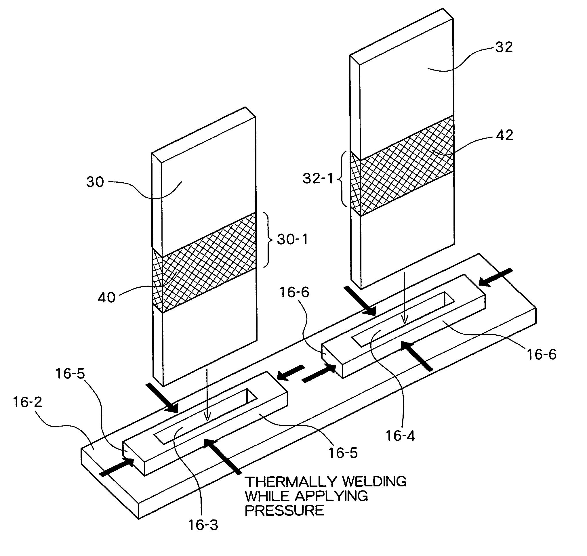
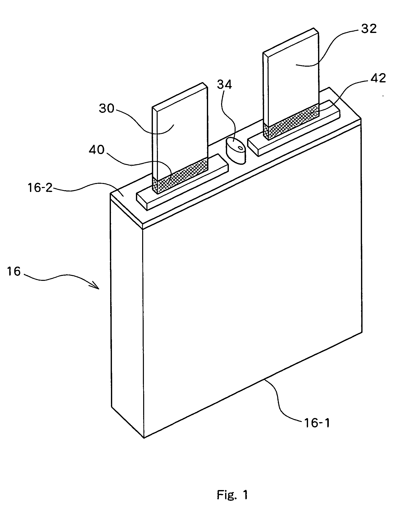
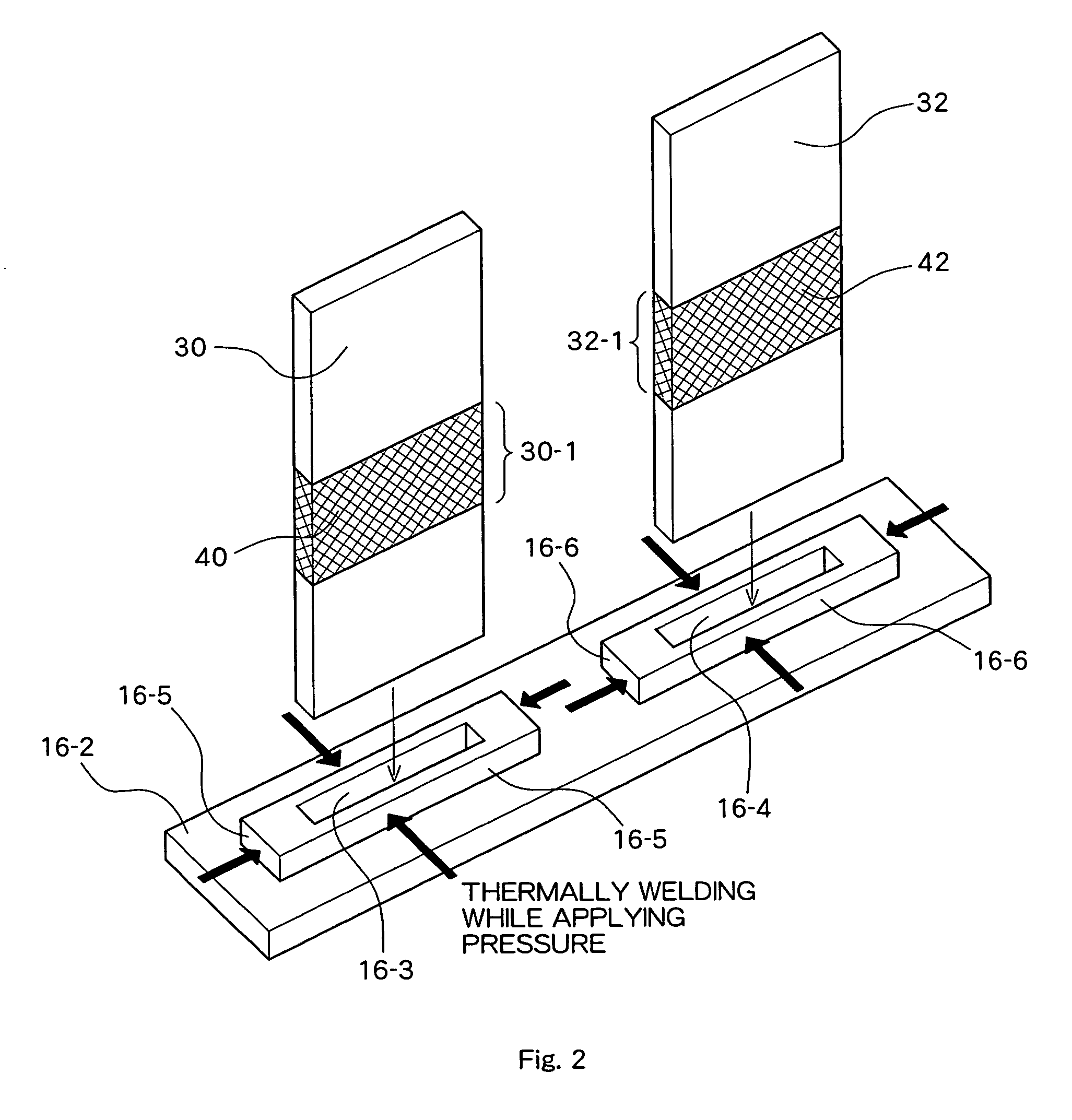
[0025] FIGS. 1 to 4 schematically show a structure of an electric double-layer capacitor according to an embodiment of the present invention. Specifically, FIG. 1 is a perspective view showing the overall appearance of the capacitor; FIG. 2 is an exploded perspective view showing a peripheral portion of positive side and negative side terminal electrodes; FIG. 3 is a perspective view showing a positive side electrode plate, and FIG. 4 is an exploded perspective view showing an electric double-layer capacitor body put away in the interior of an enclosure. In an electric double-layer capacitor according to the present embodiment, an electric double-layer capacitor body 100 includes positive side electrode plates 10 and negative side electrode plates 12 both having a flat plate shape which are arranged opposed to each other with a separator 14 being disposed between each pair of posi...


PUM

PropertyMeasurementUnit
Forceaaaaaaaaaa
Pressureaaaaaaaaaa
Electric potential / voltageaaaaaaaaaa

Abstract

A positive side terminal electrode and a negative side terminal electrode which are exposed to the exterior of a resin enclosure pass through a positive side opening and a negative side opening formed on the enclosure, respectively, and are connected to a positive side electrode and a negative side electrode, respectively, of an electric double-layer capacitor put away in the interior of the enclosure. The positive side terminal electrode is thermally welded to inner surfaces of the positive side opening over the entire periphery thereof, and the negative side terminal electrode is thermally welded to inner surfaces of the negative side opening over the entire periphery thereof.

Description

TECHNICAL FIELD [0001] The present invention relates to an electric double-layer capacitor capable of repetitive charge and discharge, an electric energy storage device including such an electric double-layer capacitor, and a manufacturing method of an electric double-layer capacitor. BACKGROUND ART [0002] Electric double-layer capacitors have been used as electric energy storage devices which can be charged and discharged repetitively. Electric double-layer capacitors are advantageous over secondary batteries that use an electrochemical reaction, in that high-speed charge / discharge using a large amount of current is possible and that they have long service life. [0003] Japanese Patent Laid-Open Publication No. Hei 4-154106 discloses technology related to electric double-layer capacitors. In this related art, an electric double-layer capacitor body formed by alternately layering positive and negative electrodes having a flat plate shape with a separator being disposed between these ...

Claims


Application Information

Patent Timeline
IPC IPC(8): H01G9/00H01G11/00H01G9/10H01G9/26H01G11/10H01G11/14H01G11/74H01G11/78H01G11/82H01G11/84
CPCH01G9/016H01G9/10H01G9/155Y10T29/417H01G11/74H01G11/82Y02E60/13H01G11/12
Inventor HIGASHI, YOJINOZU, RYUTARO
Owner JAPAN RADIO CO LTD
Why Eureka
Try Eureka