Vacuum pump

a vacuum pump and vacuum technology, applied in the direction of non-positive displacement pumps, liquid fuel engines, mechanical devices, etc., can solve the problems of increasing tightness, increasing costs, increasing tightness, etc., and reducing costs, so as to achieve the effect of reducing costs and easy replacemen

Inactive Publication Date: 2007-11-08
PFEIFFER VACUUM GMBH
View PDF9 Cites 33 Cited by
  • Summary
  • Abstract
  • Description
  • Claims
  • Application Information

AI Technical Summary

Benefits of technology

[0015]According to a further development of the present invention, the at least one vacuum chamber has an opening, and the vacuum pump further includes a releasable cover for closing the opening, and at least two seals for sealing the opening. The opening provides for an easy access to the vacuum chamber so that, e.g., maintenance becomes possible, or the components located in the vacuum chamber, e.g., of some experiment, can be very easily replaced. The opening-sealing seals insure the vacuum tightness.
[0016]The arrangement discussed above can be further improved by providing an annular channel between the two seals and in which vacuum is produced. Thereby, the pressure drop between the atmospheric pressure and vacuum takes place in stages, which reduces forces acting on the seals. Because the leakage rate of a leak depends on the pressure difference between the inner and outer si

Problems solved by technology

A smaller number of flanges and other housing transition elements becomes necessary, whereby vacuum tightness increases and expenses decreases

Method used


Image

  • Vacuum pump
  • Vacuum pump
  • Vacuum pump

Examples


first embodiment

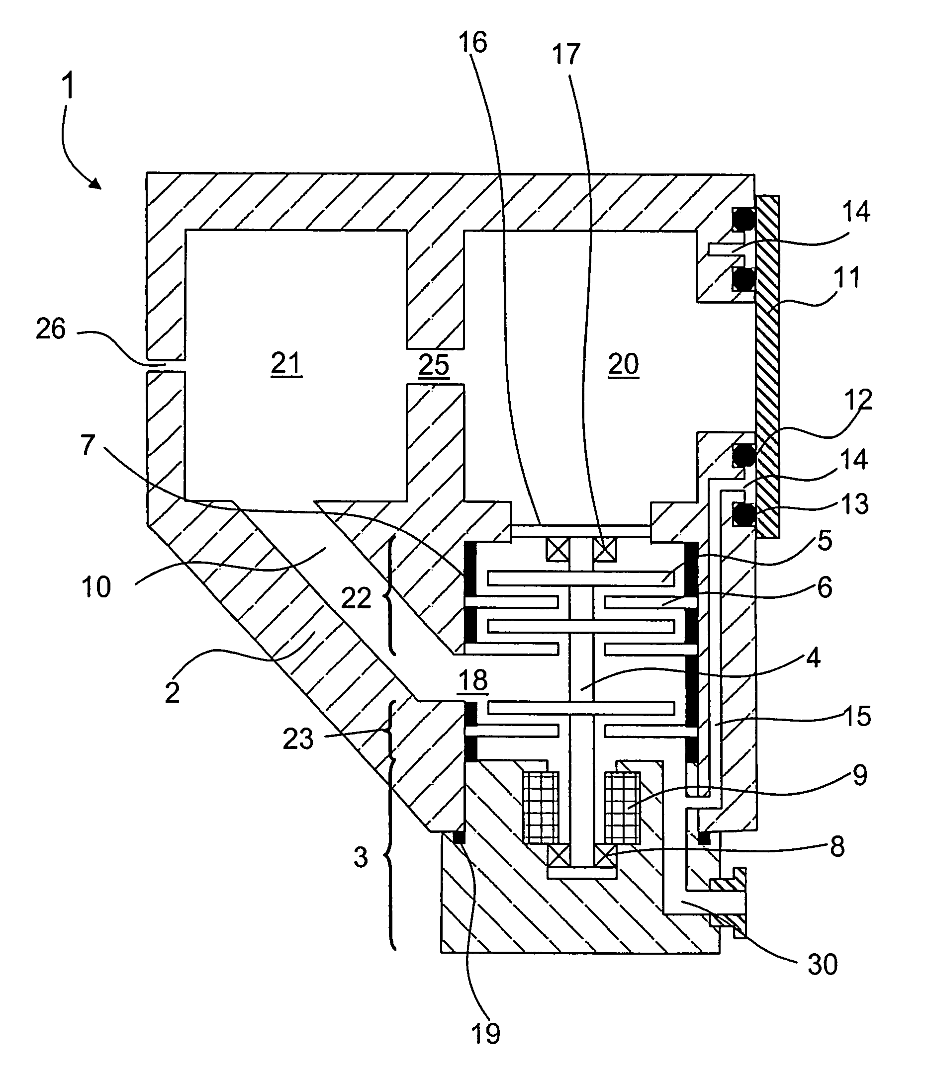
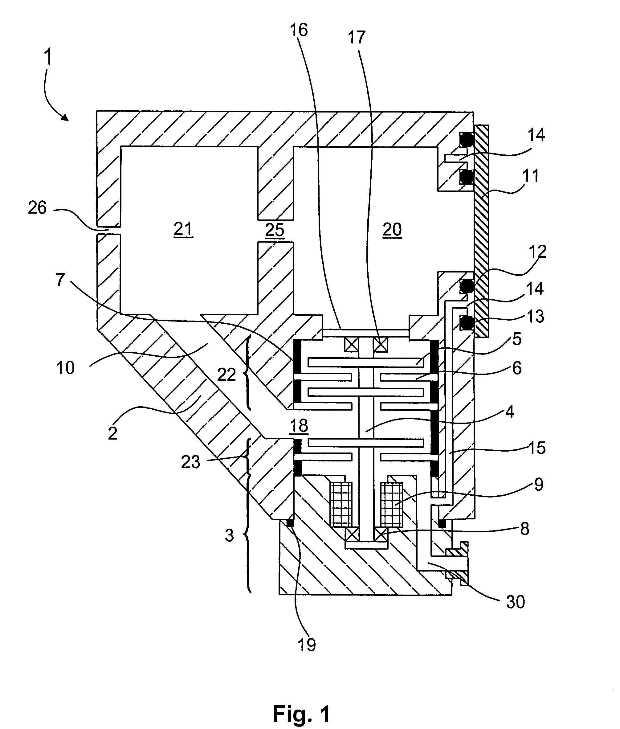
[0024]A vacuum pump 1 according to the present invention, which is shown in FIG. 1, has a housing 2 and a lower housing part 3. A shaft 4 is supported at one of its ends by bearing means 8 and at its another opposite end by a permanent magnetic bearing 17. The permanent magnetic bearing 17 is located at a high-vacuum side of the pump system and is secured thereat by a support structure 16. The pump system includes pump-active rotor elements 5 supported on the shaft 4, and stationary pump-active stator elements 6. In the embodiment shown in the drawings, rotor and stator elements are formed as blade-carrying discs, whereby a vacuum pump in accordance with a known constructional principle of turbomolecular pumps is formed. However, the present invention is not limited to this type of a vacuum pump, rather it is applicable to a combination of different types in accordance with a pressure region that should be obtained. E.g., the invention is applicable to Holweck stages and the like. T...

second embodiment

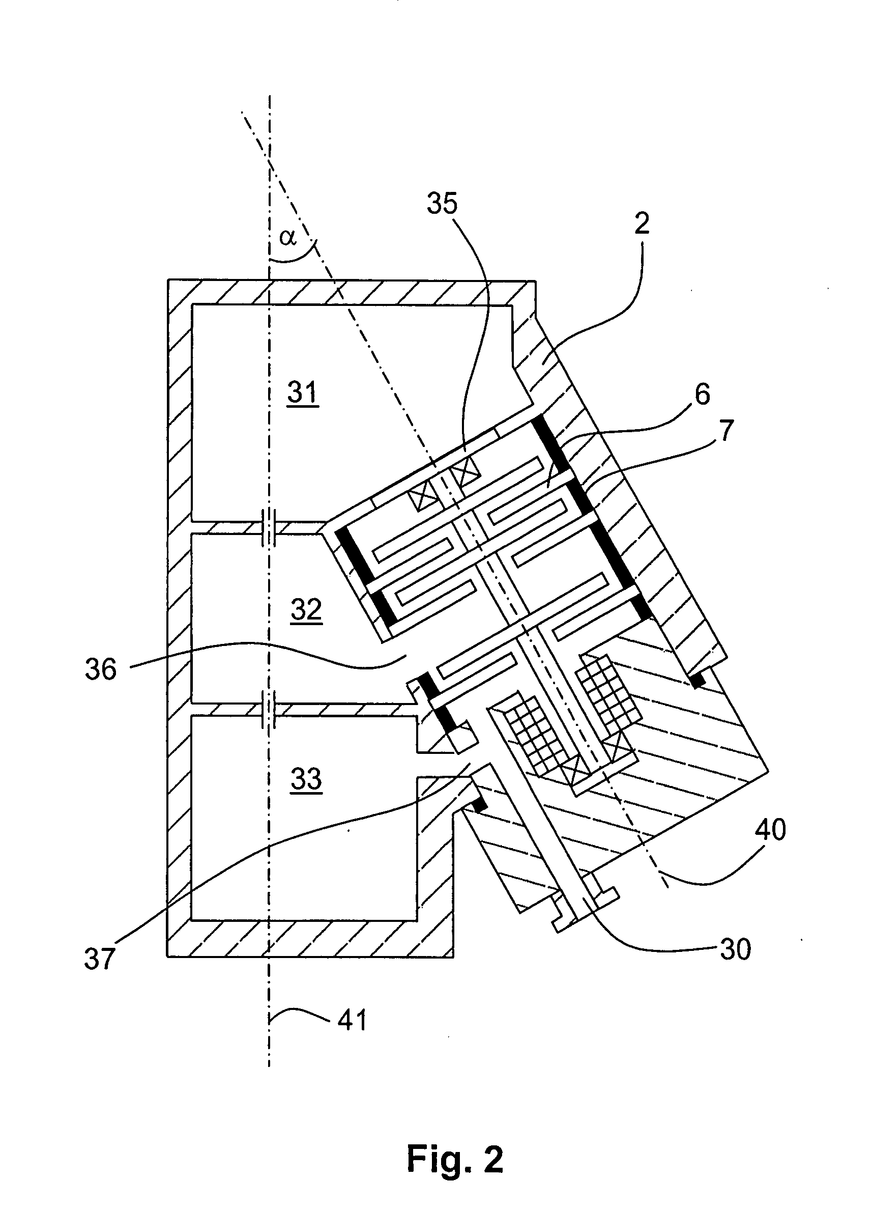
[0030]In the vacuum pump which is shown in FIG. 2, the invention is applied to a three-chamber system. There are provided in the housing 2 of the vacuum pump a first chamber 31 in which a high vacuum is produced, a second chamber 32 in which a medium vacuum is produced, and a third chamber 33. The third vacuum chamber 33 is retained at a forevacuum level. The third vacuum chamber 33 is connected via a forevacuum inlet 37 with the gas outlet channel 30 of the vacuum pump. A middle inlet 36 connects the second vacuum chamber 32 with the pumping system of the vacuum pump. A high vacuum inlet 35 connects the first vacuum chamber 31 with the pump system. Gas, which reaches the pump system through the high vacuum inlet 35 should flow over all of the parts of the pump system. The stationary components, stator discs 6 and spacers 7 should only be mounted in the housing 2 and retained in their positions. Without the housing 2, this mounting of stationary components is not possible, and rema...


PUM


Abstract

A vacuum pump includes a housing, a rotor located in the housing and having a shaft and pump-active elements supported on the shaft, a stator having pump-active elements and located in a separate housing part of the housing, for driving the pump, bearings for rotatably supporting the rotor shaft, and at least one vacuum chamber located in the housing.

Description

BACKGROUND OF THE INVENTION[0001]1. Field of the Invention[0002]The present invention relates to a vacuum pump including a housing, a rotor located in the housing and having a shaft and pump-active elements supported on the shaft, a stator located in the housing and having pump-active elements, with the housing having a housing part for holding the pump-active elements of the stator, drive means for driving the pump and bearing means for rotatably supporting the rotor shaft.[0003]2. Description of the Prior Art[0004]Vacuum pumps form, together with vacuum chambers, vacuum systems with which numerous tasks can be performed. These tasks range from manufacturing monolithic layers through analyses of gases, and up to optical columns of high-resolution electronic microscopes. The technical developments put higher and higher requirements to the vacuum tightness and compactness of the vacuum systems.[0005]In some common applications, so-called differential pumps are used. With differential...

Claims


Application Information

Patent Timeline
IPC IPC(8): F04B17/00
CPCF04D19/042F04D29/601F04D19/046
Inventor HOFMANN, BERNDSTOLL, TOBIAS
Owner PFEIFFER VACUUM GMBH
Why Eureka
Try Eureka