Guide shields for multiple component prosthetic heart valve assemblies and apparatus and methods for using them

a heart valve and multiple component technology, applied in the field of heart valves, can solve the problems of difficult to introduce the second prosthesis, the complexity of the procedure provides a greater opportunity for mistakes, and the tedious and time-consuming security of the sewing ring of either type of prosthetic valve within the target site, etc., to achieve the effect of facilitating the introduction of the second prosthesis

Active Publication Date: 2007-11-08
MEDTRONIC INC
View PDF11 Cites 288 Cited by
  • Summary
  • Abstract
  • Description
  • Claims
  • Application Information

AI Technical Summary

Benefits of technology

[0011] Optionally, the assembly may also include one or more of a sewing cuff extending outwardly from the annular member and / or a collar extending upwardly from the annular member for receiving the valve member. In addition or alternatively, the assembly may include a plurality of elongate guide rails or other leaders extending from the annular prosthesis along which a valve member may be directed. In this alternative, the guide rails may be releasably coupled to the guide members, e.g., through openings in upper ends of the guide members to bias the guide rails outwardly away from a central axis of the assembly, e.g., to improve visualization during the implantation, installation, and / or other surgical procedure.
[0015] In accordance with still another embodiment, a method is provided for implanting a heart valve assembly within a biological annulus that includes implanting a first prosthesis into the biological annulus, the first prosthesis including one or more guide members extending upwardly therefrom. A second valve prosthesis is advanced towards the first prosthesis, the second prosthesis being guided towards the first prosthesis by the one or more guide members. The one or more guide members are then removed from the first prosthesis, e.g., before or after securing the second prosthesis to the first prosthesis. In an exemplary embodiment, the guide members may be sufficiently long to extend out of the biological annulus and / or the patient's body, and the guide members may facilitate introducing the second prosthesis into the biological annulus. For example, the guide members may allow the second prosthesis to slide along an inner surface of the one or more guide members through any intervening tissue and / or may provide a smooth and / or lubricious surface along which the second prosthesis may slide during placement into the desired anatomical site. Without guide members, the friction between the surface of the second prosthesis and any intervening tissue may be so great as to require higher than desired forces to insert the second prosthesis and / or may cause the intervening tissue to buckle, collapse, and impinge the second prosthesis from reaching the desired final anatomical position within the biological annulus.

Problems solved by technology

The sewing rings of either type of prosthetic valve can be tedious and time consuming to secure within a target site, i.e., within an annulus of a heart where a natural heart valve has been removed.
Consequently, this procedure can be very complicated, requiring management and manipulation of many sutures.
The complexity of the procedure also provides a greater opportunity for mistakes and requires a patient to be on cardiopulmonary bypass for a lengthy period of time.
Because the annulus of the heart may not match the circular cross-section of the sewing ring and / or prosthetic valve, the prosthetic valve may not fit optimally within the annulus.
As a result, natural blood hemodynamics through and around the valve may be impaired, resulting in clotting, possible emboli production, and eventual calcification of the valve structure.
When a mechanical or prosthetic valve is then attached to the sewing ring, however, the valve and sewing ring may not mate together effectively, e.g., if the shape of the sewing ring has been distorted to conform to the annulus, which may also impair natural blood hemodynamics, create leaks, and / or otherwise impair performance of the prosthetic valve.
Thus, conventional procedures for implanting prosthetic heart valves may not be compatible with less invasive or minimally invasive procedures.

Method used


Image

  • Guide shields for multiple component prosthetic heart valve assemblies and apparatus and methods for using them
  • Guide shields for multiple component prosthetic heart valve assemblies and apparatus and methods for using them
  • Guide shields for multiple component prosthetic heart valve assemblies and apparatus and methods for using them

Examples


Embodiment Construction

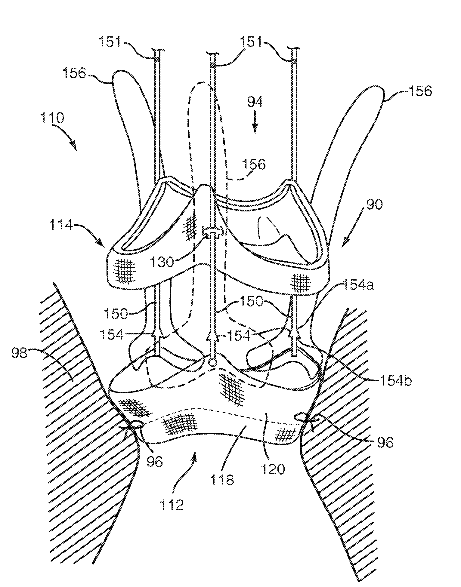
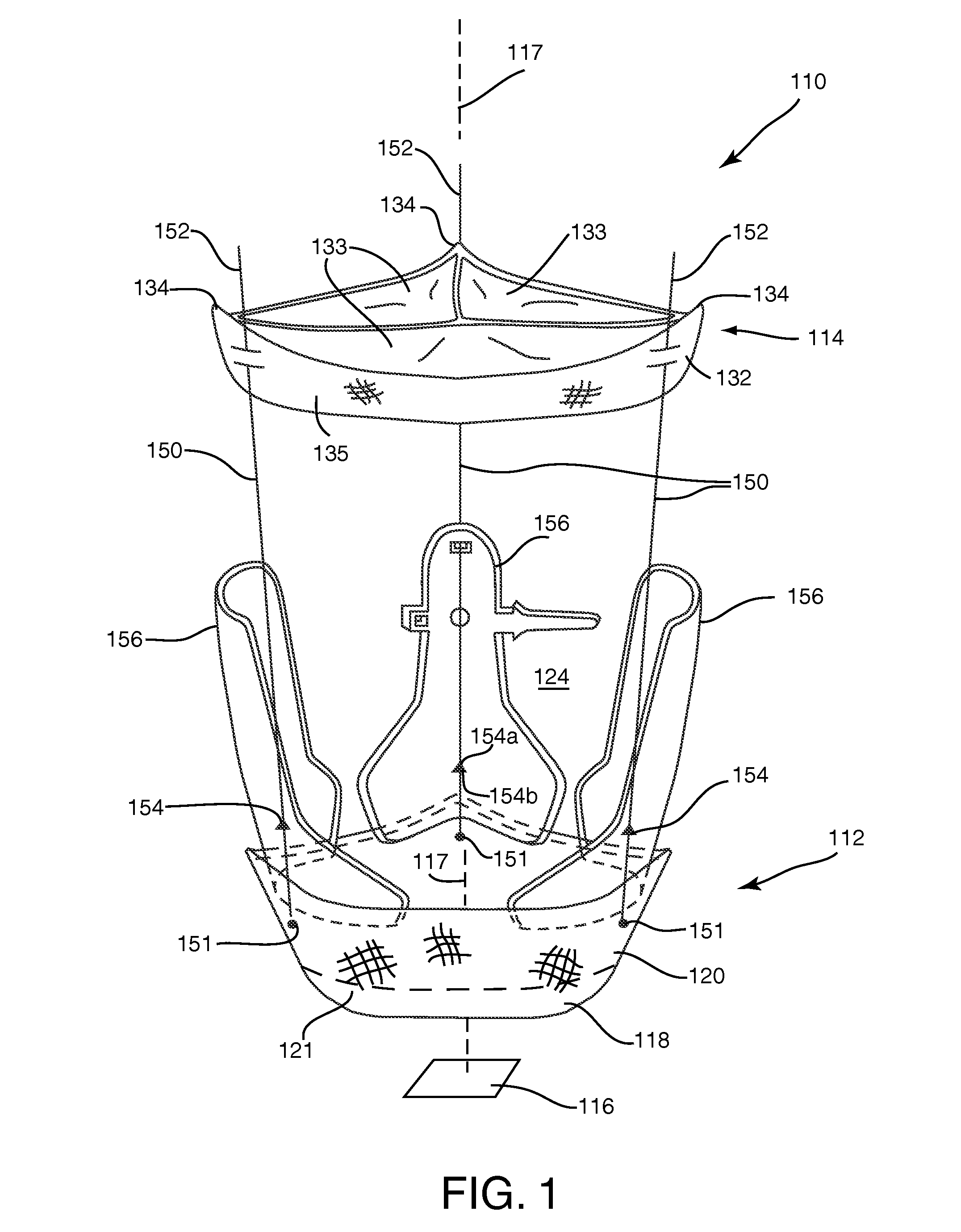
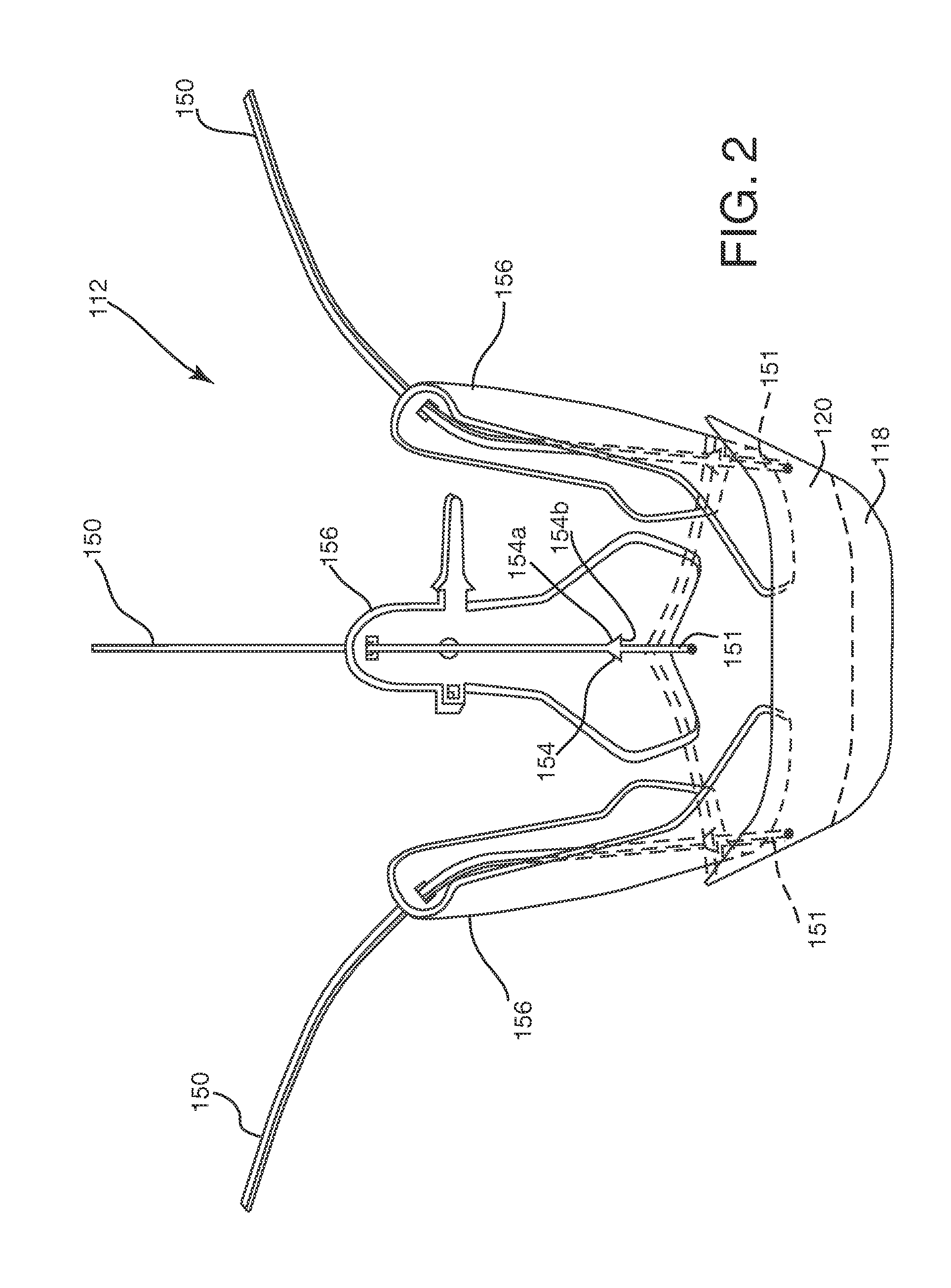
[0029] Turning to the drawings, FIGS. 1 and 2 shows an embodiment of a heart valve assembly 110 that generally includes a gasket member 112 and a valve member 114. The gasket member 112 is an annular shaped body generally defining a plane 116 and a central longitudinal axis 117 extending substantially perpendicular to the plane 116. As shown, the gasket member 112 includes an annular ring 118, a sewing cuff 120, a plurality of elongate guide rails, leaders, or other elements 150 extending from the sewing cuff 120 or other portion of the gasket member 112, and a plurality of guide shields 156 removably attached to the gasket member 112. A fabric covering 121 may be provided on one or more components of the gasket member 112, e.g., over the annular ring 118 and / or over a core of the sewing cuff 120, as described further below.

[0030] In one embodiment, the annular ring 118 may have a generally circular shape. Alternatively, the annular ring 118 may have a multi-lobular shape about the...


PUM


Abstract

A heart valve assembly includes an annular prosthesis and a plurality of guide shields removably attached around a circumference of the annular prosthesis. A plurality of elongate guide rails extend from the annular prosthesis, which are releasably retained by the guide shields. During use, the annular prosthesis is directed into a biological annulus, e.g., with the guide rails retained by the guide shields, and secured to tissue surrounding the biological annulus using fasteners. The guide rails are released from the guide shields, and a valve prosthesis is advanced over the leaders and through a passage defined by the guide shields towards the annular prosthesis. The guide rails may include retentions elements that secure the valve prosthesis to the annular prosthesis. The guide shields are removed from the annular prosthesis, the guide rails are separated from the annular prosthesis, and are removed from the biological annulus.

Description

RELATED APPLICATION DATA [0001] This application claims benefit of co-pending provisional application Ser. Nos. 60 / 746,038, filed Apr. 29, 2006, and 60 / 914,742, filed Apr. 29, 2007, the entire disclosures of which are expressly incorporated by reference herein.FIELD OF THE INVENTION [0002] The present invention relates generally to heart valves that may be implanted within a patient, and, more particularly, to multiple component heart valve assemblies that may be assembled together, and to apparatus and methods for guiding and / or otherwise facilitating assembly of components of multiple component heart valve assemblies during implantation. BACKGROUND [0003] Prosthetic heart valves can replace defective human valves in patients. For example, one piece valves have been suggested that include sewing rings or suture cuffs that are attached to and extend around the outer circumference of a prosthetic valve. In addition, multiple component valves have also been suggested that include a se...

Claims


Application Information

Patent Timeline
Patent Type & Authority Applications(United States)
IPC IPC(8): A61F2/24
CPCA61B17/0469A61B2017/00243A61F2/2409A61F2250/0063A61F2/243A61F2/2427A61F2/2418A61F2220/0083A61F2230/0006A61F2220/0008A61F2220/0033A61F2220/0075A61F2250/0069A61F2250/0091A61F2/2439A61F2/2436A61F2/2412
Inventor DREWS, MICHAEL J.GURSKIS, DONNELL W.FITTERER, MIMI NGUYENINO, TAKASHI HARRYHONG, JAMES
Owner MEDTRONIC INC
Why Eureka
Try Eureka