Storage apparatus and storage apparatus power supply failure management method

a technology for storage apparatuses and power supply failures, applied in error detection/correction, instruments, computing, etc., can solve the problems of low workability of inspection work and analytical work, inaccurate reading and writing of data, and damage to devices, so as to enhance the workability of failure analysis work and enhance maintainability

Active Publication Date: 2007-11-08
GOOGLE LLC
View PDF20 Cites 34 Cited by
  • Summary
  • Abstract
  • Description
  • Claims
  • Application Information

AI Technical Summary

Benefits of technology

[0012]With the foregoing in mind, an object of the present invention is to provide a storage apparatus and storage apparatus power supply failure management method constituted so as to be able to enhance the workability of failure analysis work by maintaining information related to a power failure on a data processing board. Another object of the present invention is to provide a storage apparatus and storage apparatus power supply failure management method constituted so as to ensure reliability and enhance maintainability by using the power supply voltage of an auxiliary power supply and writing information related to a power-failure into a storage part subsequent to immediately shutting down the power supply part in which the failure was detected. Additional objects of the present invention should become clear from the disclosures of the embodiments explained hereinbelow.

Problems solved by technology

This is because when a digital circuit malfunctions due to an abnormality of the power supply voltage, this malfunction is likely to cause the reading and writing of data that is not accurate.
For example, in a LSI (Large Scale Integration), which utilizes a plurality of types of power supply voltages, if one of those types of power supply voltage continues to operate for a long period of time in a shutdown state, this could also result in device damage.
However, since there is no information indicating which of the control board's power supply voltages generated an abnormality, a worker at the repair center installs the control board in which the power supply abnormality occurred in a storage apparatus for test use, and attempts to recreate the power supply abnormality.
Therefore, it takes a long time to specify the malfunctioning member and figure out the cause of the failure, making the workability of inspection work and analytical work low.

Method used


Image

  • Storage apparatus and storage apparatus power supply failure management method
  • Storage apparatus and storage apparatus power supply failure management method
  • Storage apparatus and storage apparatus power supply failure management method

Examples


first embodiment

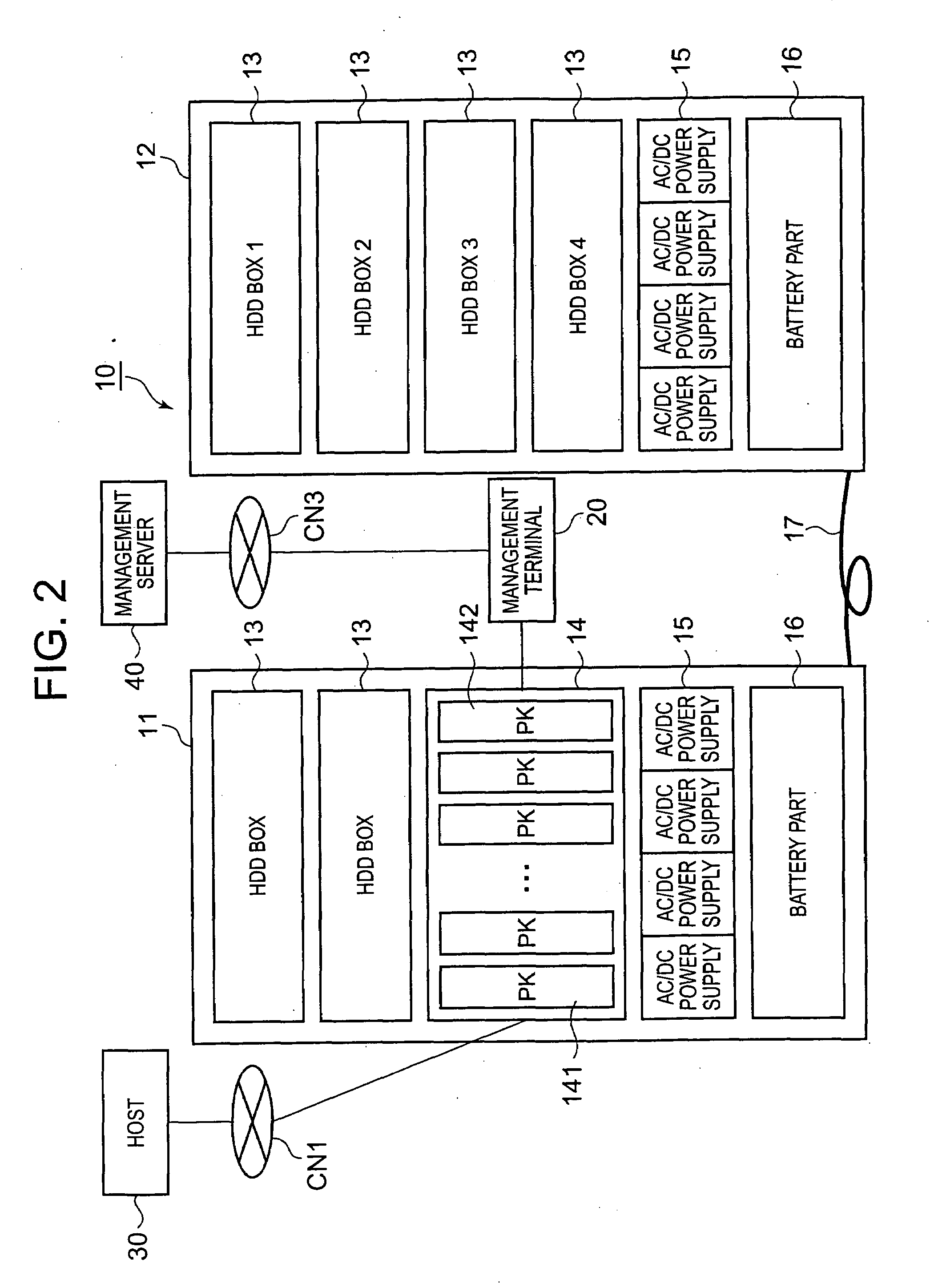
[0066]FIG. 2 is a diagram schematically showing the overall constitution of a storage system comprising a storage apparatus. This storage system, for example, can comprise a storage apparatus 10, a management terminal 20, a host 30, and a management server 40.

[0067]The details of the storage apparatus 10 will be explained hereinbelow. The management terminal 20, for example, is constituted as a computer device, such as a personal computer, or mobile information device, and, for example, is connected to the control package 142 of the storage apparatus 10 by way of a LAN or other such communication network CN2 (refer to FIG. 3). Further, the management terminal 20 can also be connected to the management server 40 via a LAN, the Internet or some other communication network CN3. The management server 40 can be connected to a plurality of management terminals 20, and, for example, can perform statistical analysis on power supply failure information collected by the respective management ...

second embodiment

[0119]A second embodiment of the present invention will be explained on the basis of FIG. 8 through FIG. 11. The following embodiments, to include this embodiment, correspond to variations of the first embodiment. In the following explanation, the focus of the explanation will be on the points of difference with the first embodiment. In this embodiment, a CHA 141, which is one example of a data processing board, is constituted in two tiers from a plurality of boards 201, 202, and information related to a power supply failure detected in a plurality of boards 202 is stored in shared memory 261.

[0120]FIG. 8 is a diagram schematically showing the board constitution of a CHA 141. As shown in the oblique view of FIG. 8(a), this CHA 141, for example, is constituted from a base board 201, and a plurality of MP boards 202, which are mounted on one side of the base board 201. The base board 201 corresponds to the “first board”, and the MP boards 202 correspond to the “second boards”. As also...

third embodiment

[0135]A third embodiment will be explained based on FIG. 12, FIG. 13, and FIG. 14. In this embodiment, a plurality of CHA 141 constitute a cluster, and when a power supply abnormality is detected in the base board 201 of any one of the CHA 141, the occurrence of the power supply abnormality is notified to a host 30 by way of another cluster of CHA 141.

[0136]FIG. 12 is a diagram schematically showing the main constitution of a storage apparatus 10 of this embodiment. In this embodiment, two CHA 141 constitute a cluster. As shown in the left side of FIG. 12, when a power supply abnormality occurs in the base board 201 of the CHA 141 on the one side, the power supply controller 211 of the base board 201 shuts down the operation of all the DC / DC power supplies 221. This shuts down the functionality of the data transfer circuit 231A. The power supply controller 211 notifies the CHA 141 of the other system (the partner CHA 141 comprising the cluster, which is the CHA shown in the right si...


PUM


Abstract

A storage apparatus according to the present invention can store information related to a power supply abnormality after shutting down the principal functions of a data processing board when a power supply abnormality occurs in a data processing board. A power supply controller of a data processing board mounted in the storage apparatus monitors the operational status of DC/DC power supplies mounted to the data processing board, on the basis of detection signals from a voltage detection circuit. When a power supply abnormality is detected, the power supply controller immediately shuts down the operation of all the DC/DC power supplies. Shutting down the DC/DC power supplies also shuts down the principal functionality of the data processing board. Then, after storing information related to the power supply abnormality in memory, the power supply controller shuts down the auxiliary power supply. The information stored in memory can be transmitted to a management apparatus by way of an intermediary apparatus, which is another data processing board or the like.

Description

CROSS-REFERENCE TO RELATED APPLICATIONS[0001]This application relates to and claims priority from Japanese Patent Application No. 2006-114039 filed on Apr. 18, 2006, the entire disclosure of which is incorporated herein by reference.BACKGROUND OF THE INVENTION[0002]1. Field of the Invention[0003]The present invention relates to a storage apparatus and a storage apparatus power failure management method.[0004]2. Description of the Related Art[0005]A storage apparatus comprises a storage part, which is connected to a plurality of hard disk drives in an array, and provides a logical storage region (logical volume) to a server or other such host computer (hereinafter, “host”).[0006]To enhance reliability and availability, a storage apparatus provides a host with redundant storage regions based on RAID (Redundant Array of Independent Disks). A storage apparatus such as this comprises at least one or more control boards. This control board controls the exchange of data with the host, and ...

Claims


Application Information

Patent Timeline
Patent Type & Authority Applications(United States)
IPC IPC(8): G06F11/00
CPCG06F1/30
Inventor OKADA, NAOKINAGAYA, HIDEHIRONAKAMURA, SHIN
Owner GOOGLE LLC
Why Eureka
Try Eureka