
Isolating Plates and Imaging Array of Crystal Lattices and the Method of Making the Same

Inactive Publication Date: 2007-11-15
INST NUCLEAR ENERGY RES ROCAEC
View PDF5 Cites 15 Cited by
  • Summary
  • Abstract
  • Description
  • Claims
  • Application Information

AI Technical Summary

Benefits of technology

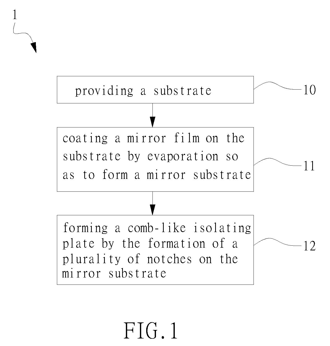
[0007]The primary object of the present invention is to provide an inexpensive method for manufacturing comb-like isolating plates, being adapted to be easily assembled into an array of lattices, by means of evaporation and laser cutting.
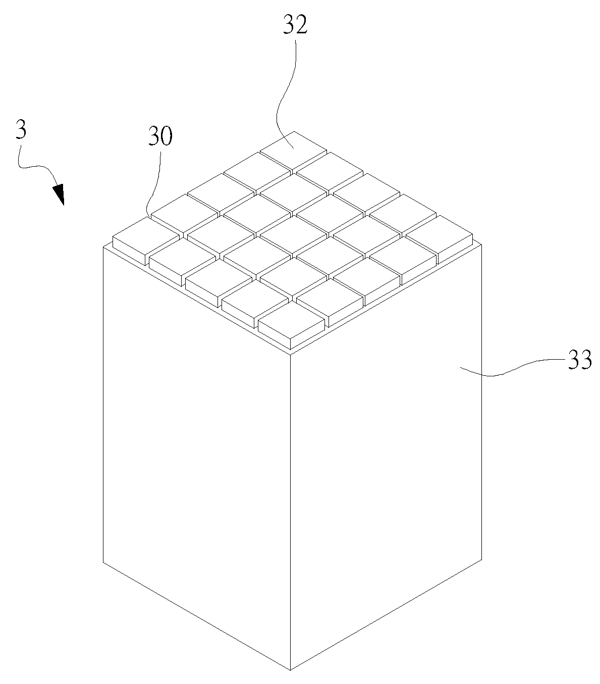
[0008]It is another object of the invention to provide an isolating plate and the imaging array manufactured thereby as well as the manufacturing methods of the two. The imaging array is accomplished by enabling each lattice of an array, which is configured of a plurality of such isolating plates, to receive an individual scintillator segment. Thus the light-collecting ability of the imaging array is enhanced while enabling the same to create comparatively clear images.

Problems solved by technology

Although the forgoing method of making a scintillation crystal array by the assembly of a plurality of comb-like mirror films is preferred, it is difficult to implement.
The first difficulty encountered is the selection of material used for making the mirror film.
It is because that the strong gradient electric field will cause an array composed of metal mirror film to accumulate static therein, and thus the electric field of the accumulated static will have adverse affect on the electric field gradient of the photomultiplier tube that it will eventually weaken the signal amplifying ability of the photomultiplier tube.
However, not only the VM 2000 is pricey, but also it is no longer in production and thus it is difficult to acquire.
Another difficulty relating to the process is laser cutting.
That is, during the assembly of the crystal array by clipping the notches of the comb-like isolating plates to each other, the comb-like isolating plates can not fixedly clip to each other and thus the assembled crystal array is prone to fall apart since the larger-than-0.1 mm notch can not grip fixedly onto the 0.06 mm substrate.
Therefore, it is difficult to accomplish the assembly since any newly configured comb-like isolating plate can fall of at any time during the assembly.
Moreover, even when an assembly is accomplished and each grid thereof is enabled to receive an individual scintillator segment, the resulting scintillation crystal array is still a loose structure that a further process is required for holding the loose structure into a rigid block.

Method used


Image

  • Isolating Plates and Imaging Array of Crystal Lattices and the Method of Making the Same
  • Isolating Plates and Imaging Array of Crystal Lattices and the Method of Making the Same
  • Isolating Plates and Imaging Array of Crystal Lattices and the Method of Making the Same

Examples


Embodiment Construction

[0025]For your esteemed members of reviewing committee to further understand and recognize the fulfilled functions and structural characteristics of the invention, several preferable embodiments cooperating with detailed description are presented as the follows.

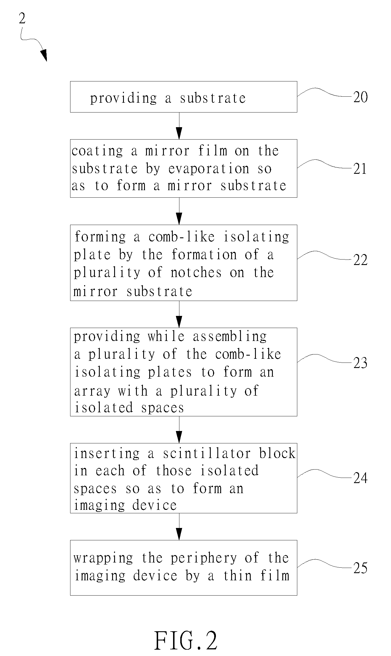
[0026]Please refer to FIG. 1, which is a flow chart depicting a method for manufacturing an isolating plate for imaging array according to a preferred embodiment of the invention. The method of FIG. 1 starts at step 10. At step 10, a substrate is provided, whereas the substrate can be a plastic substrate made of a plastic material, such as polyvinyl chloride (PVC), polyethelyne (PE), or a polyester film, etc., but is not limited thereby; and then the flow proceeds to step 11. At step 11, a mirror film is coated on the two surface of the substrate so as to form a mirror substrate with light reflecting ability, and then the flow proceeds to step 12. In a preferred aspect, the coating of the mirror film is processed by a means o...


PUM


Abstract

A method for making isolating plates for imaging array of crystal lattices, which comprises steps of: providing a substrate; coating a mirror film on the substrate by evaporation so as to form a mirror substrate; and, forming a comb-like isolating plate by the formation of a plurality of notches on the mirror substrate. By assembling a plurality of the comb-like isolating plates to form an array with a plurality of isolated spaces. After inserting a scintillator segment in each of those isolated spaces, an imaging array of crystal lattices for gamma ray detection in nuclear medicine can be manufactured. The imaging device of the invention is preferred since it is easy to assemble, inexpensive, and exhibits desirable imaging and light condensing effects.

Description

FIELD OF THE INVENTION[0001]The present invention relates to an imaging probe for nuclear medicine medical imaging device and the manufacturing method thereof, and more particularly, to an crystal array capable of forming images basing on the radiation energies detected thereby, and the isolating plate structure suitable to be applied in the crystal array.BACKGROUND OF THE INVENTION[0002]Gamma imaging probe is the key component for nuclear medicine medical imaging devices, which is used for converting gamma rays into electrical signals while using the same for location positioning. Almost every available gamma imaging probe is manufactured basing on a scintillation radiation detector, that it is basically a scintillator block coupled to a photomultiplier tube as the scintillator block is used for detecting the gamma rays emitted from radioactive substances while converting the same into corresponding visible light to be guided to the photomultiplier tube through the light-guide surf...

Claims


Application Information

Patent Timeline
IPC IPC(8): G01T1/20
CPCG01T1/1644
Inventor LIANG, HSIN-CHIN
Owner INST NUCLEAR ENERGY RES ROCAEC
Learn More