Rotor for automotive alternator having improved magnet holder
Inactive Publication Date: 2007-11-15
DENSO CORP
View PDF5 Cites 20 Cited by
Summary
Abstract
Description
Claims
Application Information
AI Technical Summary
This helps you quickly interpret patents by identifying the three key elements:
Problems solved by technology
Method used
Benefits of technology
Benefits of technology
[0020]It is, therefore, a primary object of the present invention to provide a rotor for a rotating electrical machine which includes an improved magnet holder that can securely hold and protect the permanent magnets without reducing the space available for the field coil and complicating the assembly of the rotor.
[0026]Using the non-magnetic metal material, the magnet holder can be easily formed through pressing, bending, and joining processes.
[0027]Consequently, compared to the conventional magnet holder disclosed in U.S. Pat. No. 5,925,964, the manufacturing cost can be considerably reduced.
[0028]Further, using the non-magnet metal material, it is possible to make the magnet holder very thin while securing sufficient strength of the magnet holder.
[0029]Furthermore, since each of the connecting portions of the magnet holder extends only through the radially inner side of the distal end portion of the corresponding claw to connect the end portions of the adjacent two holding portions, the space available for winding a field coil around the first and second pole cores is considerably increased in comparison with the conventional magnet holder.
[0030]Consequently, it is possible to set both the wire turns and wire diameter of the field coil to desirable values, thereby enhancing the efficiency of the rotating electrical machine.
Problems solved by technology
However, for formation of the magnet holder by resin molding, a complicated mold is required due to the complexity of shape of the magnet holder, thus increasing the manufacturing cost.
However, the mold release agent usually adheres to the work and thus remains on the surface of the resultant magnet holder.
Consequently, in fitting the magnet holder between the claws of the pole cores by adhesion, it is difficult to secure sufficient adhesion strength.
In addition, since the magnet holder is made of a resin material, it may be damaged during assembly of the rotor due to an excessive force applied thereon.
Consequently, both the parts count and the steps of assembly of the rotor are increased, thus increasing the manufacturing cost.
Consequently, due to the additional process of toothing, the manufacturing cost is further increased.
Method used
Image
Click on the blue label to locate the original text in one second.
Reading with bidirectional positioning of images and text.
Examples
first embodiment
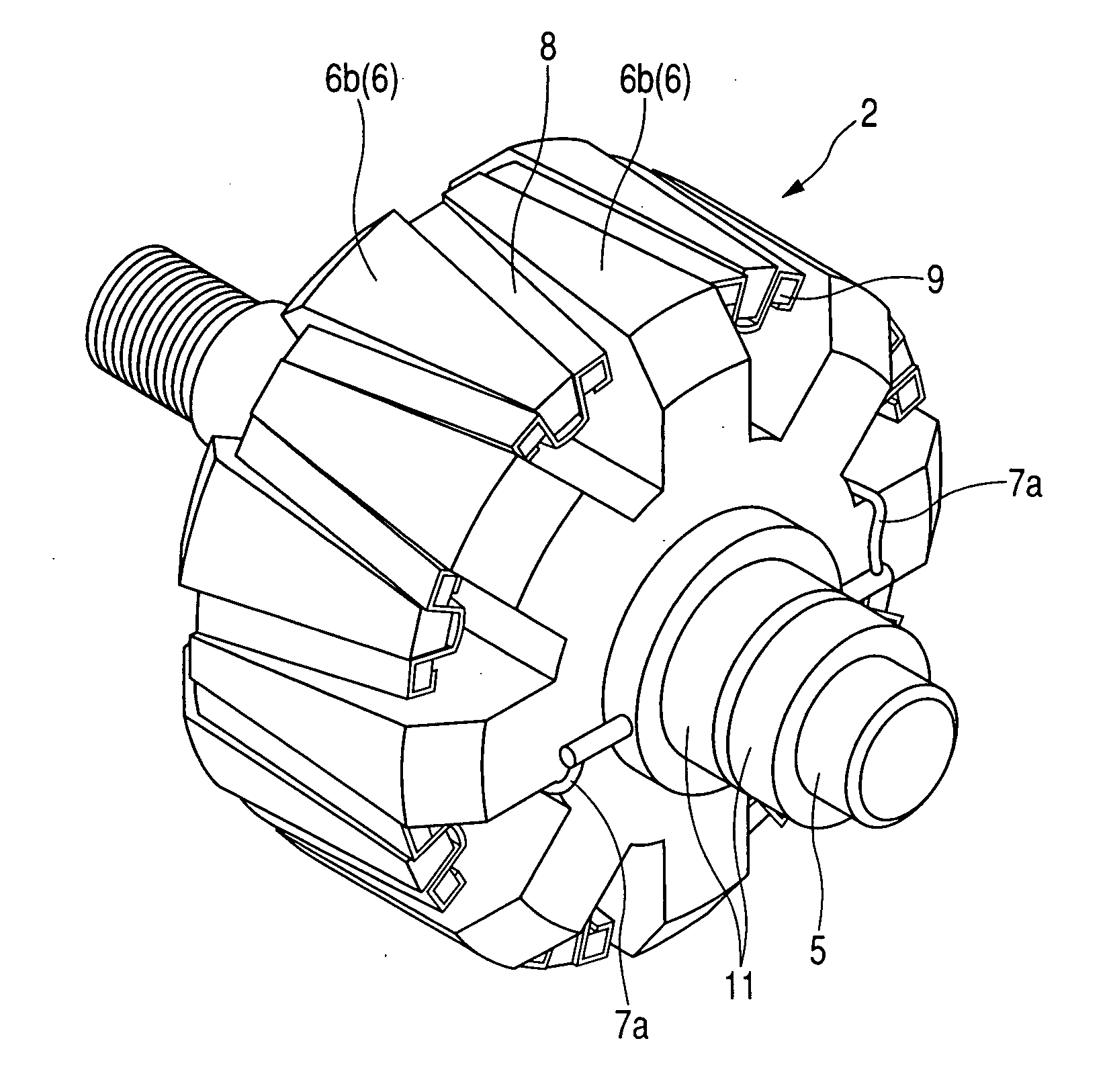
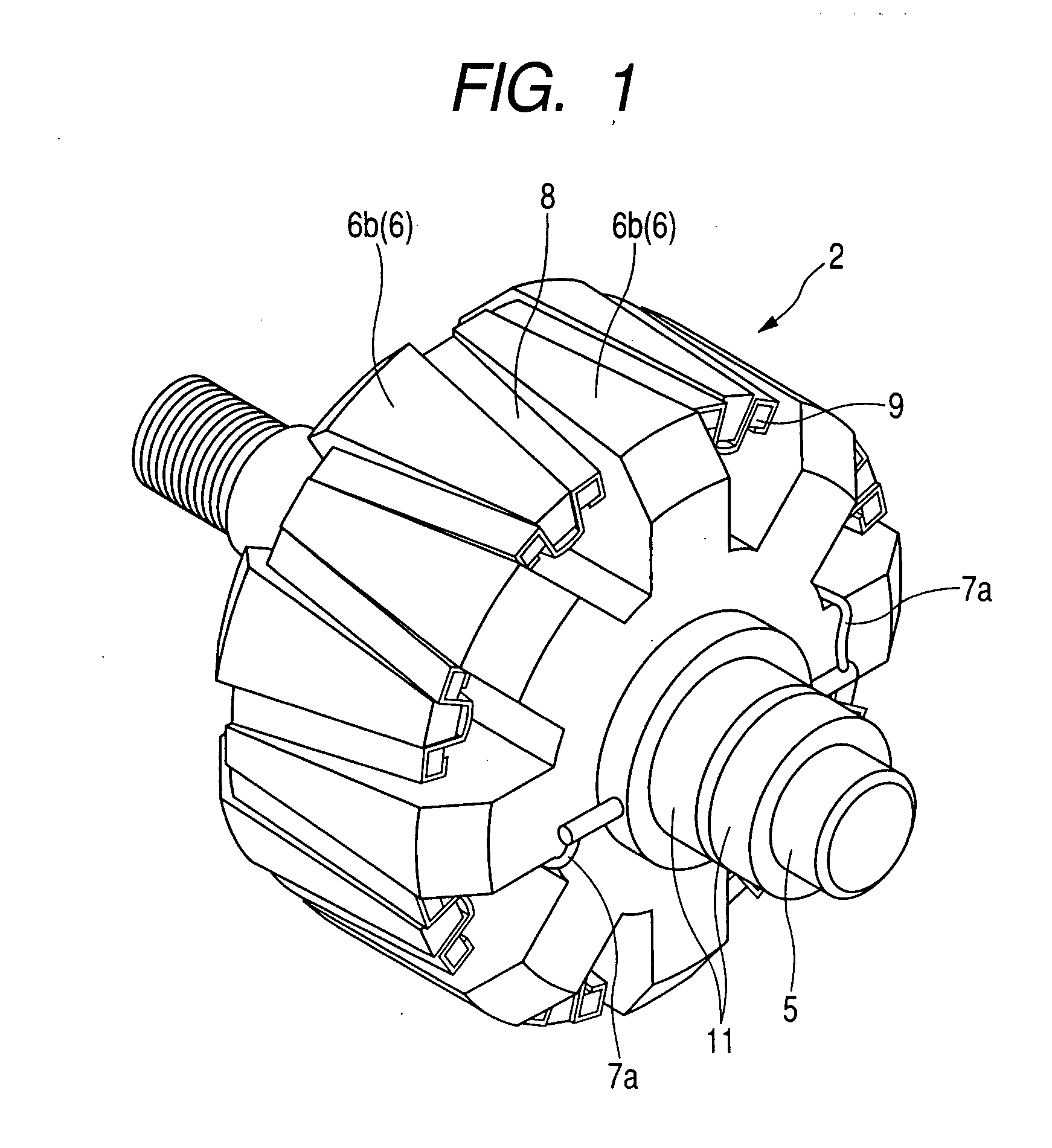
[0062]FIG. 1 shows the overall configuration of a rotor 2 according to the first embodiment of the invention. FIG. 2 shows part of an alternator 100 for a vehicle which includes the rotor 2.
[0063]As shown in FIG. 2, the alternator 100 includes a stator 1, which works as an armature, and the rotor 2 that works as a field.
[0064]The stator 1 includes a stator core 3 and a stator coil 4. The stator core 3 has a hollow cylindrical shape so as to surround the rotor 2. The stator coil 4 is wound around the stator core 3, so that AC current is generated in the stator coil 4 when the rotor 2 rotates.
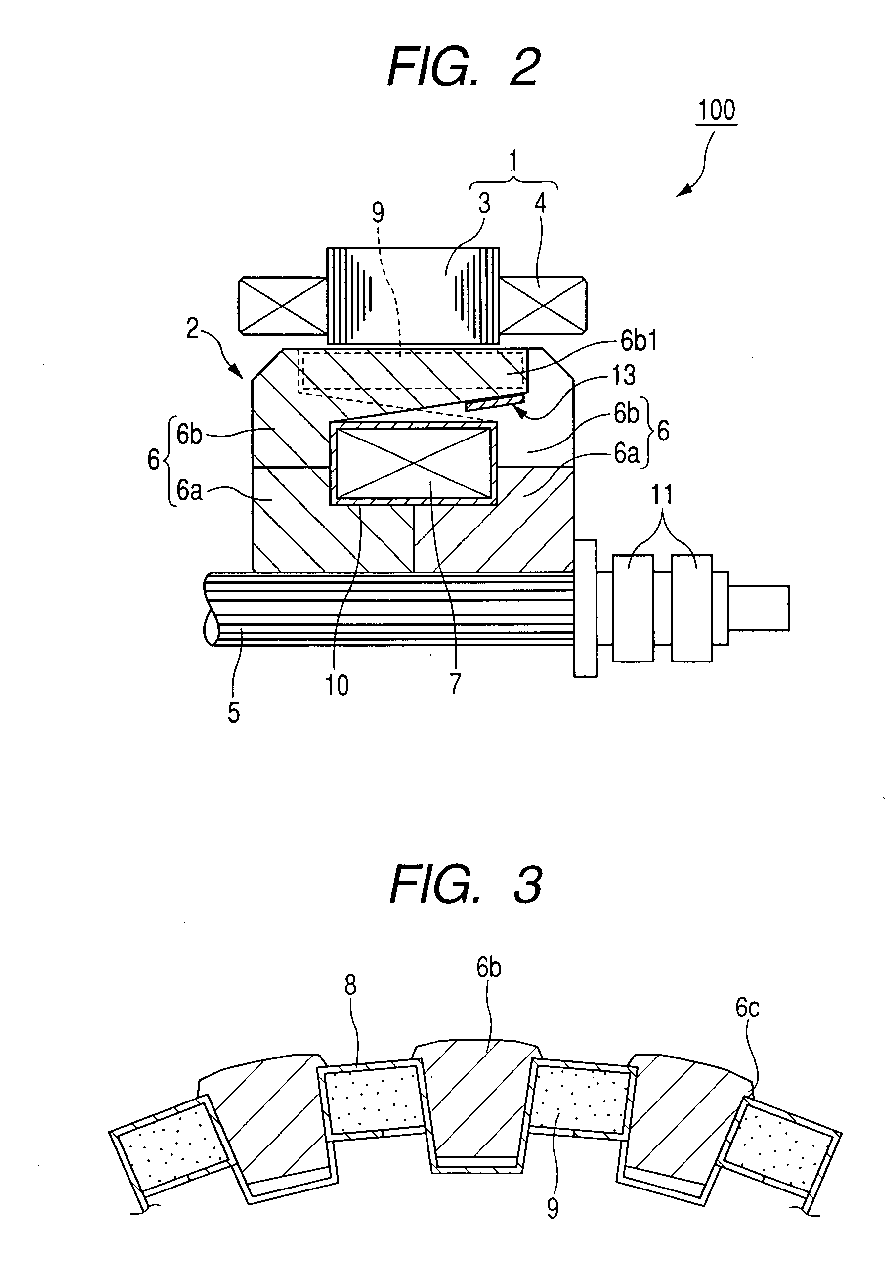
[0065]The rotor 2 includes a rotary shaft 5, a pair of lundell-type pole cores 6, a field coil 7, a magnet holder 8, a plurality of permanent magnets 9, and slip rings 11.
[0066]The rotary shaft 5 is configured to be driven by an engine of the vehicle. On a rear end portion of the rotary shaft 5, there is provided the slip rings 11 for supplying field current to the field coil 7 during rotation of...
second embodiment
[0108]FIG. 8 shows part of a magnet holder 8 according to the second embodiment of the invention, which includes, in addition to the holding portions 12 and the connecting portions 13, a plurality of abutting portions 8a.
[0109]Referring further to FIG. 9, each of the abutting portions 8a extends radially outward from one of the connecting portions 13 to abut the distal end portion 6b1 of one of the claw portions 6b of the pole cores 6 which is on the radially outer side of the one of the connecting portions 13.
[0110]The abutting portions 8a work to inhibit relative axial movement between the magnet holder 8 and the pole cores 6. Thus, with the abutting portions 8a, it is possible to accurately position the magnet holder 8 in the axial direction of the rotary shaft 5.
[0111]Consequently, the permanent magnets 9 held by the magnet holder 8 can also be accurately positioned in the axial direction, thereby reliably diminishing the magnetic flux leakage between the claw portions 6b of th...
third embodiment
[0113]FIG. 10 shows part of a magnet holder 8 according to the third embodiment of the invention.
[0114]As shown in FIG. 10, in this embodiment, each of the holding portions 12 further includes a pair of end walls 12d, each of which extends radially inward from one of the longitudinal ends of the radially outer wall 12a of the holding portion 12.
[0115]With the end walls 12d, it is possible to impede movement of the one of the permanent magnets 9 held in the holding portion 12 in the longitudinal direction of the holding portion 12. Consequently, it is possible to accurately position the one of the permanent magnets 9 in the axial direction of the rotary shaft 5.
PUM
Abstract
According to the invention, there is provided a rotor for a rotating electrical machine which includes a rotary shaft, a pair of first and second pole cores fixed on the rotary shaft, a plurality of permanent magnets, and a magnet holder holding the permanent magnets. The magnet holder is made of a non-magnetic metal and has a plurality of holding portions and a plurality of connecting portions. Each of the holding portions is interposed between circumferentially adjacent two of claws of the first and second pole cores, so as to hold a corresponding one of the permanent magnets between the adjacent two claws. Each of the connecting portions circumferentially extends, through the radially inner side of a distal end portion of one of the claws of the first and second pole cores, to connect end portions of adjacent two of the holding portions which circumferentially bracket the distal end portion.
Description
CROSS-REFERENCE TO RELATED APPLICATION[0001]This application is based on and claims priority from Japanese Patent Application No. 2006-134969, filed on May 15, 2006, the content of which is hereby incorporated by reference into this application.BACKGROUND OF THE INVENTION[0002]1. Technical Field of the Invention[0003]The present invention relates generally to rotating electrical machines, such as electric generators and motors. More particularly, the invention relates to a rotor for an automotive alternator which includes an improved magnet holder for holding a plurality of permanents magnets between interleaved claws of lundell-type pole cores.[0004]2. Description of the Related Art[0005]There is known a method of improving the efficiency of an automotive alternator, which includes a rotor having a pair of lundell-type pole cores, by disposing a plurality of permanent magnets between the pole cores.[0006]More specifically, each of the lundell-type pole cores is secured on a rotary ...
Claims
Application Information
Patent Timeline
Application Date:The date an application was filed.
Publication Date:The date a patent or application was officially published.
First Publication Date:The earliest publication date of a patent with the same application number.
Issue Date:Publication date of the patent grant document.
PCT Entry Date:The Entry date of PCT National Phase.
Estimated Expiry Date:The statutory expiry date of a patent right according to the Patent Law, and it is the longest term of protection that the patent right can achieve without the termination of the patent right due to other reasons(Term extension factor has been taken into account ).
Invalid Date:Actual expiry date is based on effective date or publication date of legal transaction data of invalid patent.

