
Prefabricated PCM and battery pack containing the same

Active Publication Date: 2007-11-15
LG ENERGY SOLUTION LTD
View PDF4 Cites 12 Cited by
  • Summary
  • Abstract
  • Description
  • Claims
  • Application Information

AI Technical Summary

Benefits of technology

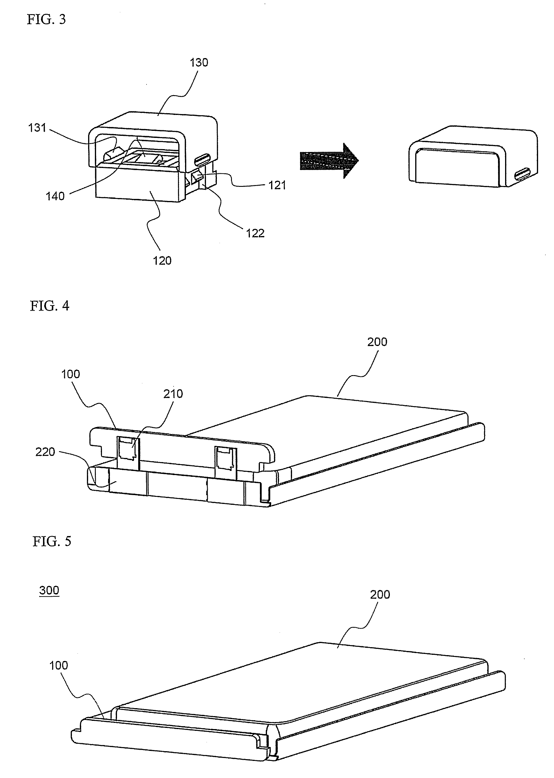
[0009] As a result of a variety of extensive and intensive studies and experiments to solve the problems as described above, the inventor of the present application has discovered that, when plate-shaped electrode terminals of a battery cell are inserted into a protection circuit module (PCM), to which specific-structure connecting members and coupling members are mounted, and then the inserted electrode terminals are bent so as to constitute a battery pack, a welding or soldering process, which requires a large amount of time and a high degree of technical skill to manufacture a battery pack, is not necessary, the coupling force between the battery cell and the PCM is increased, the electrically connecting force between the electrode terminals of the battery cell and the PCM is increased, and the inner space of the battery pack is maximally utilized.
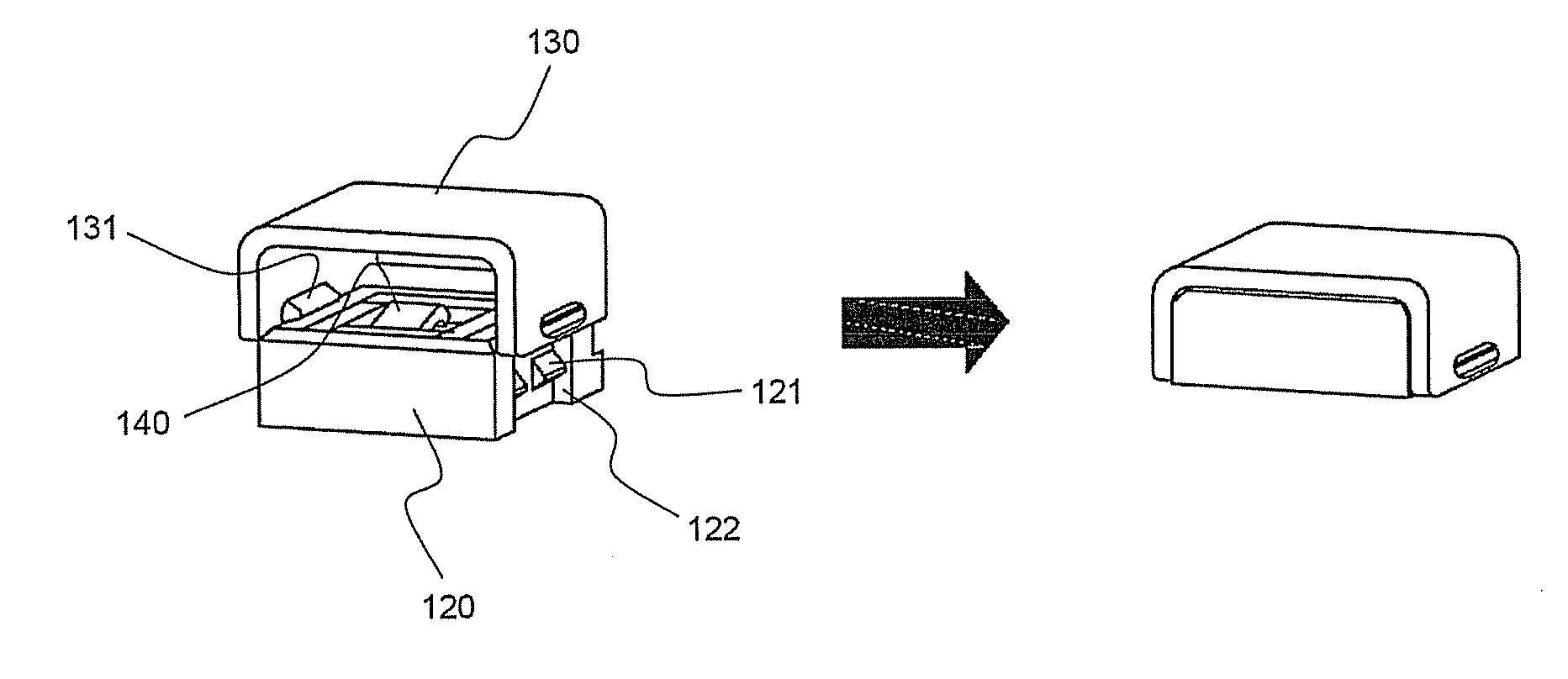
[0015] In a preferred embodiment, the connecting members, on which the electrode terminals of the battery cell are mounted, and the coupling members, which are coupled to the connecting members while the electrode terminals of the battery cell are mounted on the connecting members such that the coupling members surround the corresponding connecting members, are separated from each other, and the connecting members and the coupling members have coupling parts, which are constructed in a complementary structure to increase the coupling force between the connecting members and the coupling members.
[0018] The coupling members are constructed in a structure in which the outer surfaces (the front surfaces) of the coupling members, in the direction in which the electrode terminals are introduced to be located on the connecting members, are open, and the opposite surfaces (the rear surfaces) of the coupling members are open or closed. Preferably, the coupling members are constructed in a structure in which the rear surfaces of the coupling members are partially or entirely closed so as to prevent the occurrence of short circuits due to the protrusion of the electrode terminals during the assembly of the battery pack or during the use of the battery pack.
[0020] The coupling between the connecting members and the coupling members may be accomplished in another exemplary structure. Each of the coupling members may be rotatably connected to one side of each of the connecting members, and each of the coupling members may be provided at the other side thereof with a coupling part for coupling each coupling member and the corresponding connecting member. Consequently, after the electrode terminals are located at the connecting members while the connecting members and the coupling members are separated from each other, the coupling members are rotated such that the corresponding coupling parts can be coupled to each other, whereby the connection between the PCM and the electrode terminals is easily accomplished.

Problems solved by technology

However, various combustible materials are contained in the lithium secondary battery.
As a result, there is a possibility of danger in that the lithium secondary battery can be heated or explode due to overcharge, overcurrent, or any other external physical impacts.
In other words, the lithium secondary battery has low safety.
However, the welding or soldering process requires a high degree of technical skill with the result that skilled persons are needed.
Also, the welding or soldering process requires large working space.
Furthermore, when physical impacts are applied to the battery cell, electrical shorts may occur, and therefore, the battery cell may catch fire or explode.
In other words, safety-related problems may occur.
However, the above-described methods are not suitable for a battery cell including various kinds of electrode terminals, such as plate-shaped electrode terminals.
Furthermore, the protection circuit and the electrode terminals are electrically connected with each other merely through the contact between the protection circuit and the electrode terminals, and therefore, the connecting force between the protection circuit and the electrode terminals is also low.

Method used


Image

  • Prefabricated PCM and battery pack containing the same
  • Prefabricated PCM and battery pack containing the same
  • Prefabricated PCM and battery pack containing the same

Examples


Embodiment Construction

[0029] Now, preferred embodiments of the present invention will be described in detail with reference to the accompanying drawings. It should be noted, however, that the scope of the present invention is not limited by the illustrated embodiments.

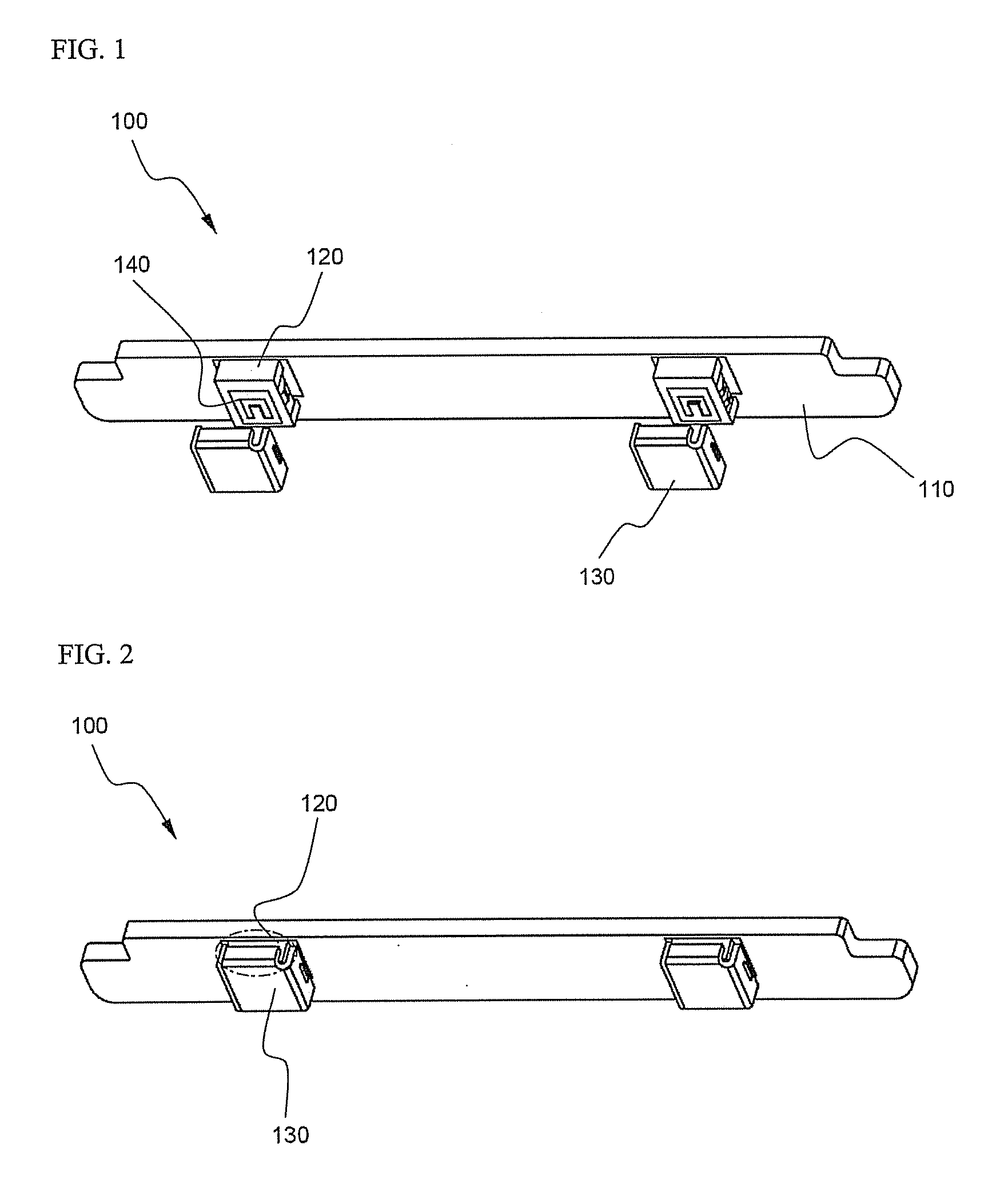
[0030]FIGS. 1 and 2 are perspective views illustrating a prefabricated protection circuit module (PCM) according to a preferred embodiment of the present invention before and after coupling members are coupled, respectively.

[0031] Referring to these drawings, the PCM 100 is formed in a printed circuit board (PCB) structure in which a protection circuit (not shown) for controlling overcharge, overdischarge, and overcurrent of a battery is printed to a rectangular-structure epoxy composite body.

[0032] At the lower end 110 of the PCM 100 are formed connecting members 120, which are electrically connected to the protection circuit. Coupling members 130 are structural bodies, which are coupled to the connecting members 120 while electrode ter...


PUM


Abstract

Disclosed herein is a protection circuit module (PCM) including a protection circuit for controlling overcharge, overdischarge, and overcurrent of a battery. The protection circuit module includes a pair of connecting members, which are mounted to a rectangular lower end of the PCM and electrically connected to a protection circuit, and a pair of coupling members coupled to the corresponding connecting members while plate-shaped electrode terminals of a battery cell are interposed between the connecting members and the coupling members, and a battery pack including the protection circuit module, which is electrically connected to a battery cell. According to the present invention, a welding or soldering process, which requires a large amount of time and a high degree of technical skill to manufacture a battery pack, is not necessary, the coupling force between the battery cell and the PCM is increased, and the inner space of the battery pack is maximally utilized.

Description

FIELD OF THE INVENTION [0001] The present invention relates to a protection circuit module (PCM) including a protection circuit for controlling overcharge, overdischarge, and overcurrent of a battery, and, more particularly, to a protection circuit module including a pair of connecting members, which are mounted to a rectangular lower end of the PCM and electrically connected to a protection circuit, and a pair of coupling members coupled to the corresponding connecting members while plate-shaped electrode terminals of a battery cell are interposed between the connecting members and the coupling members, and a battery pack including the protection circuit module, which is electrically connected to a battery cell. BACKGROUND OF THE INVENTION [0002] As mobile devices have been increasingly developed, and the demand of such mobile devices has increased, the demand of secondary batteries has also sharply increased. One of the secondary batteries is a lithium secondary battery having hig...

Claims


Application Information

Patent Timeline
IPC IPC(8): H02J7/00H01M50/572
CPCH01M2/34H01M10/052H01M2200/00H01M10/425H01M10/4207Y02E60/10H01M50/572H02H7/18
Inventor LEE, DONGCHEOLYOON, SEOGJINKIM
Owner LG ENERGY SOLUTION LTD
Learn More