Eureka AIR delivers breakthrough ideas for toughest innovation challenges, trusted by R&D personnel around the world.

Cylindrical Roller Bearing

a technology of cylindrical rollers and bearings, applied in bearings, shafts and bearings, rotary machine parts, etc., can solve the problems of heat generation and abrasion in some cases, and the contact part of the cylindrical roller and the flange is likely to be a hotspot for so as to reduce the contact surface pressure and prevent heat generation and abrasion. , the effect of reducing the pressur

Inactive Publication Date: 2007-11-15
NTN CORP
View PDF4 Cites 10 Cited by
  • Summary
  • Abstract
  • Description
  • Claims
  • Application Information

AI Technical Summary

Benefits of technology

[0027] Preferably, in order to improve the lubricant state of the sliding contact part between the cylindrical roller and the flange of the track ring, the height “h” of the chamfer is made smaller than the height “H” of the relief groove from the track surface.
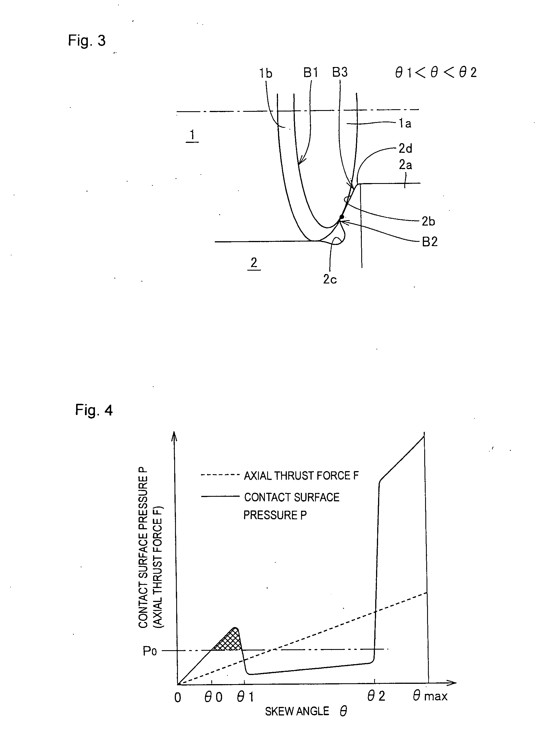
[0029] As described above, according to the present invention, the heat generation and the abrasion at the contact part can be prevented by further reducing the contact surface pressure of the contact part between the cylindrical roller and the flange of the track ring.

Problems solved by technology

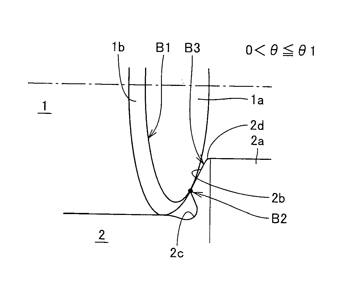
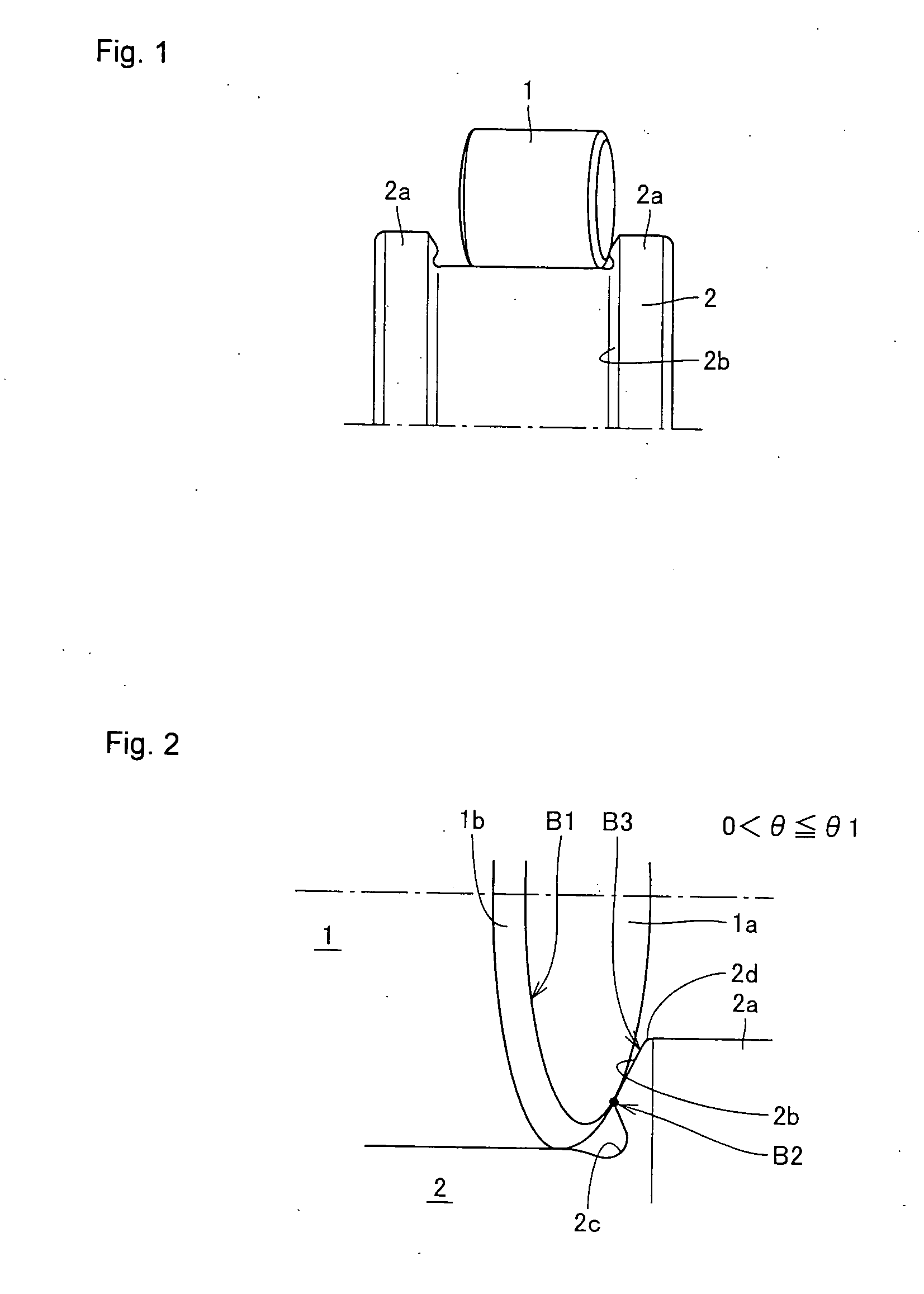
According to the cylindrical roller bearing described above, since the rolling surface of the cylindrical roller and the track surface of the track ring are linearly in contact with each other, it has a high load facility of a radial load and it is suitable for high-speed rotation, but a heating value is great at the time of high-speed rotation as compared with a boll bearing, and it has a problem in that a lot of heat and abrasion are likely to be generated at the sliding contact part between the cylindrical roller and the flange, especially.
Thus, the friction resistance at the sliding contact part between the cylindrical roller and the flange surface is increased, which causes heat generation and abrasion in some cases.
However, according to the above Japanese Patent Publication No. 58-43609, there is no recognition of the above phenomenon, so that its measures are not proposed.

Method used


Image

  • Cylindrical Roller Bearing
  • Cylindrical Roller Bearing
  • Cylindrical Roller Bearing

Examples


Embodiment Construction

[0038]FIG. 7 shows a cylindrical roller bearing 10 according to one embodiment of the present invention. The cylindrical roller bearing 10 is used in a high-load and high-speed rotating operation in a wind power generation speed-up gear, a machine tool, a jet engine, a gas turbine and the like.

[0039] The cylindrical roller bearing 10 comprises an inner ring 20 having a track surface 21 on its outer periphery, an outer ring 30 having a track surface 31 on its inner periphery, a plurality of cylindrical rollers 40 arranged between the track surface 21 of the inner ring 20 and the track surface 31 of the outer ring 30 so as to freely roll, and a retainer 50 retaining the plurality of cylindrical roller bearings 40 at predetermined intervals in a circumferential direction. A flange 22 is provided on each side of the inner ring 20.

[0040] As shown in an enlarged view in FIG. 8, a relief groove 23 is provided at a corner in which a flange surface 24 of the flange 22 and the track surface...


PUM


Abstract

A relief groove (23) is provided at a corner in which a track surface (21) and a flange surface (24) cross, in an inner ring (20) of a cylindrical roller bearing. A chamfer (42) is provided at a corner part in which a rolling surface (41) and an end surface (43) cross, in a cylindrical roller (40). When it is assumed that the height of the chamfer (42) from the rolling surface (41) is “h” and the curvature radius of the chamfer is “R”, the relation such that 1.0≦R / h≦1.5 is satisfied.

Description

TECHNICAL FIELD [0001] The present invention relates to a cylindrical roller bearing suitable for supporting a shaft rotating at high speed and high load in a wind power generation speed-up gear, a machine tool, a jet engine, a gas turbine and the like. BACKGROUND ART [0002] A general cylindrical roller bearing comprises an inner ring having a track surface around its outer periphery, an outer ring having a track surface around its inner periphery, a plurality of cylindrical rollers arranged between the track surface of the inner ring and the track surface of the outer ring so that they can roll freely, and a retainer retaining the cylindrical rollers at a predetermined intervals in a circumferential direction. [0003] For example, when the inner ring comprises flanges at both ends, a relief groove is provided at the corner in which the flange surface of the flange and the track surface of the inner ring cross. This relief groove is provided as a relief region when the track surface ...

Claims


Application Information

Patent Timeline
Patent Type & Authority Applications(United States)
IPC IPC(8): F16C33/58
CPCF16C19/26F16C2240/70F16C2240/40F16C33/585F16C19/225F16C33/34F16C2240/42
Inventor TSUMORI, YUKIHISAOYA, YOSUKE
Owner NTN CORP
Why Eureka
Eureka Blog
Learn More