Method of application protocol monitoring for programmable logic controllers

a programmable logic controller and protocol monitoring technology, applied in the field of programmable logic controllers, can solve the problem that network monitoring tools do not have the capability or information required to determine if, and achieve the effect of reducing vehicle launch tim

Active Publication Date: 2007-11-15
FORD MOTOR CO
View PDF40 Cites 15 Cited by
  • Summary
  • Abstract
  • Description
  • Claims
  • Application Information

AI Technical Summary

Benefits of technology

[0009] One advantage of the present invention is that a method of application protocol monitoring is provided for monitoring programmable logic controllers used in a manufacturing line to manufacture a motor vehicle. Another advantage of the present invention is that the method has the ability to sit parasitically on a network and monitor source and destination traffic, and reuse model based data originating in an upstream control logic simulation model. Yet another advantage of the present invention is that the method significantly reduces vehicle launch time by enabling a user from a single location to directly wa

Problems solved by technology

A major problem faced during launch of a vehicle and new equipment start-ups on the manufacturing line is assuring that various devices receive the appropriate control signals.
However, these network monitoring

Method used


Image

  • Method of application protocol monitoring for programmable logic controllers
  • Method of application protocol monitoring for programmable logic controllers
  • Method of application protocol monitoring for programmable logic controllers

Examples


Embodiment Construction

)

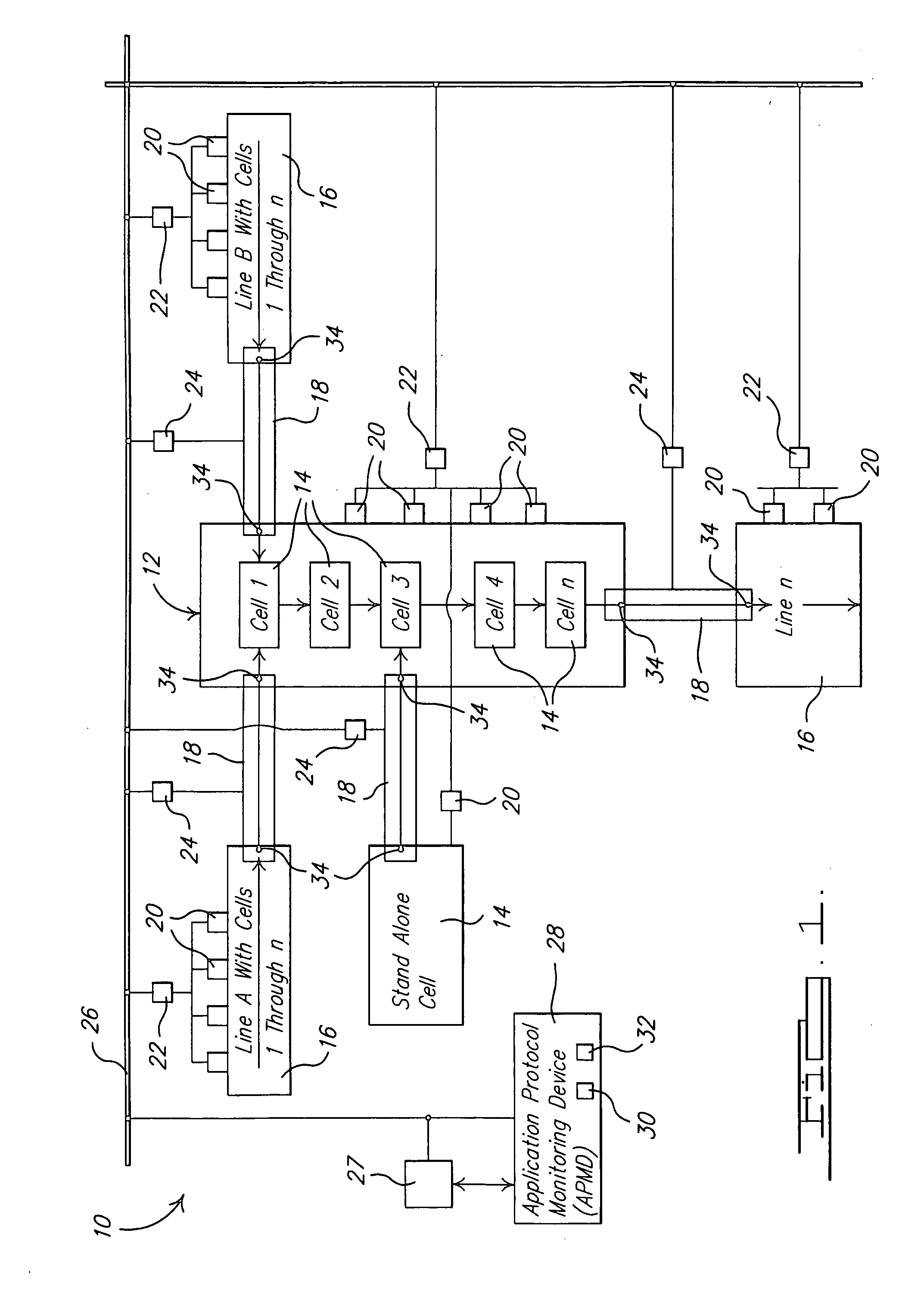
[0015] Referring to the drawings and in particular FIG. 1, one embodiment of a system 10, according to the present invention, for application protocol monitoring for a manufacturing line, generally indicated at 12, is illustrated. The manufacturing line 12 includes at least one, preferably a plurality of workcells 14. The workcells 14 are grouped together in at least one, preferably a plurality of workcell lines 16. The manufacturing line 12 may include at least one, preferably a plurality of material handling / transfer (MH) systems 18. One of the MH systems 18 is located between a pair of workcell lines 16 such that the MH system 18 transfers material between the workcell lines 16. It should be appreciated that there may be a standalone workcell 14 and that one MH (MH) system 18 is disposed between the standalone workcell 14 and a workcell line 16. It should also be appreciated that the workcell line 16 may have one or more workcells 14, e.g., cell 1, cell 2, cell 3, cell 4, to cel...


PUM


Abstract

A method is provided of application protocol monitoring for a manufacturing line including the steps of constructing a manufacturing line model for the manufacturing line, utilizing logic for a programmable logic controller (PLC), executing a control logic simulation of the PLC logic to validate the PLC logic against the manufacturing line model, creating a database containing validated I/O tag expected intents confirmed from the control logic simulation, and applying the application protocol monitoring device to a network for the manufacturing line to monitor traffic across the network and continuously compare the I/O tag status across the network to the database of validated I/O tag expected intents.

Description

BACKGROUND OF THE INVENTION [0001] 1. Field of the Invention [0002] The present invention relates generally to programmable logic controllers and, more specifically, to a method of application protocol monitoring for programmable logic controllers for manufacturing a motor vehicle. [0003] 2. Description of the Related Art [0004] It is known that programmable logic controller (PLC) code is written by controls engineers after assembly tooling designs are completed and a manufacturing process has been defined. Once the programmable logic controller code is written, it is used by programmable logic controllers to control and monitor machine tools used in the manufacture of parts and assemblies for motor vehicles. [0005] It is also known that a manufacturing line is typically made of three to twenty linked workcells. Each workcell consists of a tool such as a fixture to position a product, for example sheet metal, and associated automation, for example robots, that process the product, f...

Claims


Application Information

Patent Timeline
IPC IPC(8): G06F19/00
CPCG05B19/4185G06F11/3692G05B2219/32337G05B19/41885Y02P90/02
Inventor COBURN, JAMESWALACAVAGE, JOE
Owner FORD MOTOR CO
Why Eureka
Try Eureka