Antenna and wireless communication device

a wireless communication and antenna technology, applied in the direction of separate antenna unit combinations, resonant antennas, radiating element structural forms, etc., can solve the problems of not being able to meet the demand for low-voltage operation, not being able to significantly change the third resonant frequency, and not being able to change the resonant frequency. , to achieve the effect of reducing the effect of the resonant frequency of the electrode connected to the series resonance circuit and the small antenna

Active Publication Date: 2007-11-22
MURATA MFG CO LTD
View PDF13 Cites 58 Cited by
  • Summary
  • Abstract
  • Description
  • Claims
  • Application Information

AI Technical Summary

Benefits of technology

[0015] With the configuration described above, the first antenna section includes the feeding electrode, the frequency-changing circuit, and the radiating electrode, and the second antenna section includes the feeding electrode, the first reactance circuit of the frequency-changing circuit, and the additional radiating electrode. Thus, it is possible to achieve multiple resonances with a resonant frequency associated with the first antenna section and a resonant frequency associated with the second antenna section. By changing the reactance of the first reactance circuit of the frequency-changing circuit, the resonant frequency of the first antenna section and the resonant frequency of the second antenna section change simultaneously. That is, with the frequency-changing circuit, it is possible to simultaneously change a plurality of resonant frequencies by a desired range. When a wide bandwidth is to be achieved using a single-resonance antenna, it is necessary to apply a large control voltage to a frequency changing circuit so that a resonant frequency can be changed over a wide range. In contrast, with the antenna according to a preferred embodiment of the present invention, it is possible to simultaneously change a plurality of resonant frequencies with different frequencies using a low control voltage. Thus, it is possible to achieve a wide bandwidth using a low control voltage.
[0047] In one particular preferred embodiment of the present invention, when the reactance circuit is implemented by a series resonance circuit, the effect on the resonant frequency of the electrode connected to the series resonance circuit can be reduced. When the reactance circuit is implemented by a parallel resonance circuit, the constant of a load inductor can be reduced, so that the problem of a chip component regarding the self-resonant frequency can be solved. When the reactance circuit is implemented by a composite circuit including a series resonance circuit and a parallel resonance circuit, it is possible to achieve both the advantage of the series resonance circuit and the advantage of the parallel resonance circuit.

Problems solved by technology

However, the antennas according to the related art described above have the following problems.
In this example, although a complex circuit configuration is not required, since the resonance circuit is provided at the distal-end portion of the antenna element, where the electric field is most intense (current density is smallest), it is not possible to change the resonant frequency greatly.
This does not allow for satisfaction of the demand for low-voltage operation required for a wireless communication device such as a cellular phone.
However, since the third antenna element is connected in parallel to the feeding element without an intervening tuning circuit, it is not possible to change the third resonant frequency significantly.
Furthermore, since the parallel circuit is disposed in the proximity of a feeding section of the radiating element, the problems of the antenna disclosed in Patent Document 2 also exist.

Method used


Image

  • Antenna and wireless communication device
  • Antenna and wireless communication device
  • Antenna and wireless communication device

Examples


first preferred embodiment

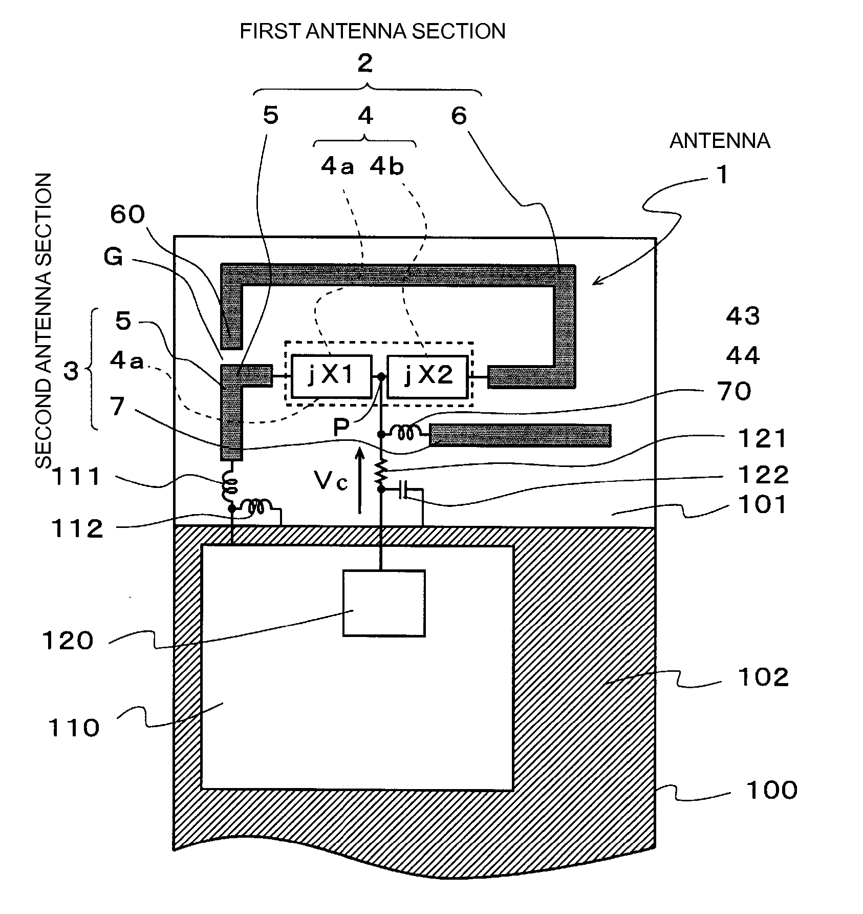
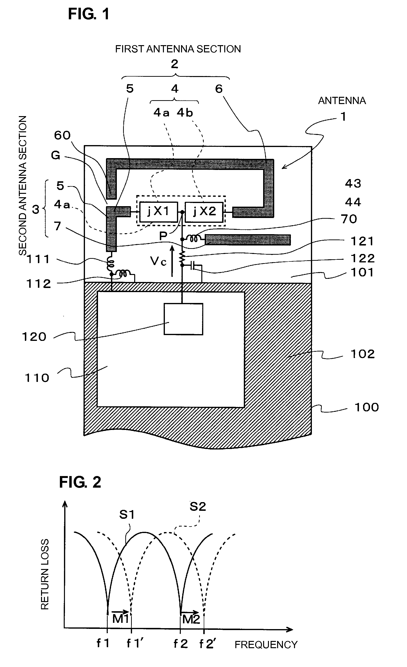
[0082]FIG. 1 is a schematic plan view showing an antenna according to a first preferred embodiment of the present invention.

[0083] An antenna 1 according to this preferred embodiment is preferably provided on a wireless communication device, such as a cellular phone.

[0084] As shown in FIG. 1, an antenna 1 is provided in a non-ground region 101 of a circuit board 100 of the wireless communication device, and the antenna 1 exchanges high-frequency signals with a transceiver 110 mounted on a ground region 102. Furthermore, a DC control voltage Vc is input to the antenna 1 from a reception-frequency controller 120 provided in the transceiver 110.

[0085] The antenna 1 includes a first antenna section 2 and a second antenna section 3, and the first and second antenna sections 2 and 3 share a frequency-changing circuit 4.

[0086] In the first antenna section 2, a radiating electrode 6 is connected to a feeding electrode 5 via the frequency-changing circuit 4. More specifically, a matching...

second preferred embodiment

[0101]FIG. 4 is a schematic plan view showing an antenna according to a second preferred embodiment of the present invention. FIGS. 5A and 5B are circuit diagrams showing specific examples of the first reactance circuit 4a preferably includes a series circuit, and FIGS. 6A-6D are circuit diagrams showing specific examples of the second reactance circuit 4b of the variable type.

[0102] In an antenna 1 according to this preferred embodiment, specific variable series circuits are used as the first reactance circuit 4a and the second reactance circuit 4b in the first embodiment.

[0103] The first reactance circuit 4a preferably is a series circuit including a variable capacitor or a parallel circuit including a variable capacitor. In this preferred embodiment, a series circuit including a variable capacitor is used. The series circuit including a variable capacitor may be a series circuit shown in part (a) or (b) of FIG. 5. In this example, the series circuit shown in part (a) of FIG. 5 ...

third preferred embodiment

[0108] Next, a third preferred embodiment of the present invention will be described.

[0109]FIG. 7 is a schematic plan view showing an antenna according to the third preferred embodiment of the present invention. FIGS. 8A-8E are circuit diagrams showing specific examples of the second reactance circuit 4b of the fixed type.

[0110] In the second preferred embodiment described above, a series circuit including a variable capacitor is preferably used as the first reactance circuit 4a, and a series circuit including a variable capacitor or a parallel circuit including a variable capacitor is preferably used as the second reactance circuit 4b. In this preferred embodiment, as the second reactance circuit 4b, a series circuit including a fixed capacitor or a parallel circuit including a fixed capacitor is preferably used.

[0111] The series circuit including a fixed capacitor or the parallel circuit including a fixed capacitor may be any of circuits shown in parts (a) to (e) of FIG. 8. In ...


PUM


Abstract

An antenna and a wireless communication device are adapted to have a plurality of resonant frequencies changed simultaneously by a desired range at a low voltage. The antenna includes a first antenna section and a second antenna section. The first antenna section includes a feeding electrode, a frequency-changing circuit, and a radiating electrode, and the second antenna section includes the feeding electrode, a first reactance circuit, and an additional radiating electrode. The frequency-changing circuit has a circuit configuration in which the first reactance circuit and the second reactance circuit are connected. When a control voltage Vc is applied to a node P, the reactances of the first and second reactance circuits change in accordance with the magnitude of the control voltage Vc, so that a resonant frequency f1 of the first antenna section and a resonant frequency f2 of the second antenna section change simultaneously.

Description

BACKGROUND OF THE INVENTION [0001] 1. Field of the Invention [0002] The present invention relates to antennas used for wireless communications and to wireless communication devices. [0003] 2. Description of the Related Art [0004] Recently, in the field of wireless communication devices, such as cellular phones, development for achieving multiple resonances or multiple bands is in progress in order to achieve wide bandwidths. Research studies are being carried out for antennas in which a plurality of resonant frequencies are controlled to allow transmission and reception with a wide bandwidth. Also, antennas in which a frequency can be changed to achieve a wide bandwidth are being considered. [0005] Examples of such antennas that have been proposed include antennas disclosed in Patent Documents 1 to 3. [0006] An antenna disclosed in Patent Document 1 (Japanese Unexamined Patent Application Publication No. 2003-51712), is an inverted-F-shaped antenna device. More specifically, an ante...

Claims


Application Information

Patent Timeline
Patent Type & Authority Applications(United States)
IPC IPC(8): H01Q1/24H01Q5/10
CPCH01Q1/243H01Q5/371H01Q21/30H01Q9/0442
Inventor ISHIZUKA, KENICHIKAWAHATA, KAZUNARI
Owner MURATA MFG CO LTD
Why Eureka
Try Eureka