Inspection apparatus for image pickup device, optical inspection unit device, and optical inspection unit

a technology of image pickup and inspection apparatus, which is applied in the direction of measurement devices, scientific instruments, instruments, etc., can solve the problems of inferior inspection efficiency, adverse effect of pupil correction, and difficulty in carrying out inspection efficiently and consecutively, so as to reduce inspection cost, reduce size, and short time

Inactive Publication Date: 2007-11-22
OYO ELECTRIC
View PDF3 Cites 19 Cited by
  • Summary
  • Abstract
  • Description
  • Claims
  • Application Information

AI Technical Summary

Benefits of technology

[0007]The present invention has been made in view of the conventional problems as described above, and it is an object thereof, by holding a plurality of optical inspection units in a manner positioned in a plurality of openings of a probe card by a holding means, and furthermore, allowing a pupil distance adjustment for each of the inspection units, to provide an inspection apparatus for an image pickup device, an optical inspection unit device, and an optical inspection unit that can simply carry out alignment between the optical inspection units and probe card in a short time, for which the configuration of a holding portion of the optical inspection units is reduced in size, and that are capable of carrying out an efficient and consecutive light irradiation. In addition, another object of the present invention is to provide an inspection apparatus for an image pickup device, an optical inspection unit device, and an optical inspection unit that can reduce the inspection cost, without newly fabricating an optical system, by merely adjusting or replacing only the optical inspection units so as to match new image pickup devices even when the image pickup devices being an inspection target change in size while a structure for which a probe card and a holding portion are integrated is used in common.
[0008]In order to achieve the object, according to the present invention, an optical inspection unit device that irradiates a test light, in a photoelectric conversion characteristic inspection of an image pickup device, while being arranged in opposition to a light receiving portion of the image pickup device is provided. The optical inspection unit device is constructed as an optical inspection unit device 52 that includes: a probe card 501 that retains a probe pin 502 to take out output from an output terminal portion 1y of an image pickup device 1 and is equipped with a plurality of openings 501a that transmit light to the image pickup device 1; an optical inspection unit 520 that irradiates the test light through the plurality of openings of the probe card while being arranged in opposition to the light receiving portion (1A) of the image pickup device; a holding means 504 that simultaneously positions and holds a plurality of optical inspection units while arranging an emission side of the optical inspection unit 520 in opposition to the light receiving portion of the image pickup device with an optical axis C of the optical inspection unit being aligned on the light receiving surface of the image pickup device 1; and an individual adjustment means 505 that makes a converting adjustment carried out, for light from a light irradiator corresponding to the image pickup device being an inspection target, so as to match the same with specifications of the image pickup device be individually carried out for each optical inspection unit. By making only the optical inspection units 520 attachable and detachable, respectively, with the optical axes being determined and aligned by the holding means, only the optical inspection units 520 are changed without basically changing the probe card and holding means even in a case where a chip being an inspection object is different in size or the like, whereby reduction in manufacturing cost, reduction in inspection preparation time, maintainability, and the like can be secured.
[0010]In addition, it is preferable that the individual adjustment means 505 includes a shifting adjustment mechanism 553 for an engagement position between the optical inspection unit 520 and holding means 504 so as to make the whole optical inspection unit 520 shiftable in an optical axis C direction, and the converting adjustment to match light from a light irradiator with specifications of the image pickup device 1 is carried out by a shifting adjustment of the engagement position by the shifting adjustment mechanism. If a pupil distance adjustment is possible by merely changing the relative position of the optical inspection unit with respect to the holding means, an individual converting adjustment can be carried out by an extremely simple method.
[0011]In addition, it is preferable that the case body has a plurality of built-in optical lenses 522, and the individual adjustment means 505 includes an axial position adjustment mechanism 530 that sets an optical-axis-direction position of the plurality of optical lenses in the case body so as to be changeable. In this case, replacement of the case body itself is unnecessary, and a converting adjustment that is carried out, for light from a light irradiator corresponding to the solid-state image pickup device, so as to match the same with specifications of the image pickup device can be carried out at a low cost by only a position adjustment of the internal optical lenses or a lens replacement according to necessity.

Problems solved by technology

In inspecting photoelectric conversion characteristics of the solid-state image pickup device performed with a pupil correction as such, if a telecentric light of a light irradiator for inspection is made incident into the solid-state image pickup device, the pupil correction adversely effects, and light quantity in the periphery of a light receiving unit of the image pickup device further declines.
Therefore, not only does an alignment operation including adjustment of a drive portion to make it possible to securely maintain an optical axis position after shifting take time, but also a high-precision mechanism is required for a drive system, and furthermore, a new optical axis adjustment is necessary after every maintenance so that there has been a problem in inferiority in inspection efficiency.
Moreover, since an alignment mechanism between the optical adapter and probe card is greater in size than the image pickup devices with a small area, it has been difficult to carry out inspection efficiently and consecutively while shifting along adjacent lines or rows of the image pickup devices integrally formed on a wafer, and the inspection has often been carried out for every other device or while shifting in an oblique direction (see FIG. 9).
Furthermore, there have been no standards between the probe card and pupil inspection optical system, it has been necessary to fabricate a probe card matched with an optical system or an optical system matched with a probe card every time, so that there has been a problem in a high inspection cost.

Method used


Image

  • Inspection apparatus for image pickup device, optical inspection unit device, and optical inspection unit
  • Inspection apparatus for image pickup device, optical inspection unit device, and optical inspection unit
  • Inspection apparatus for image pickup device, optical inspection unit device, and optical inspection unit

Examples


Embodiment Construction

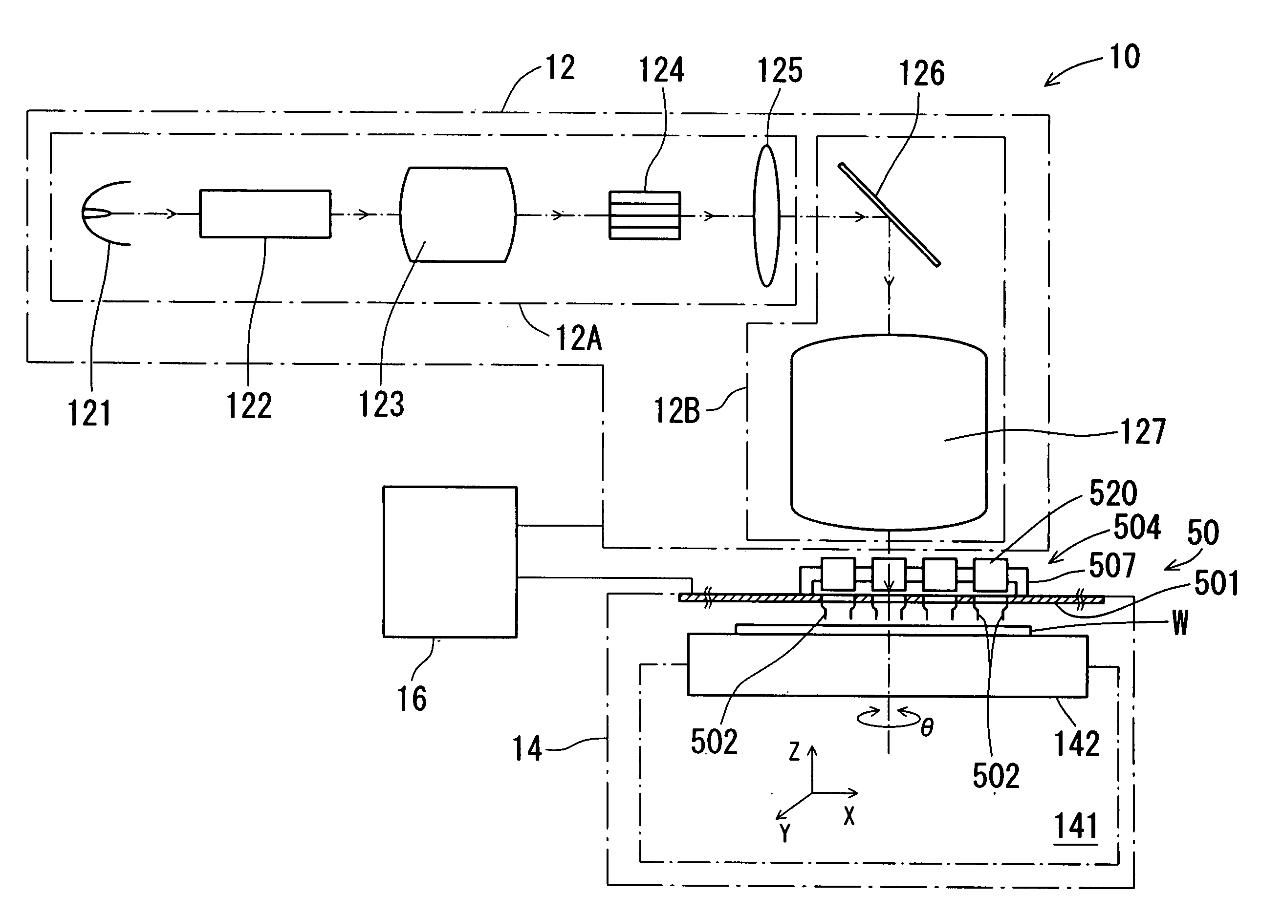
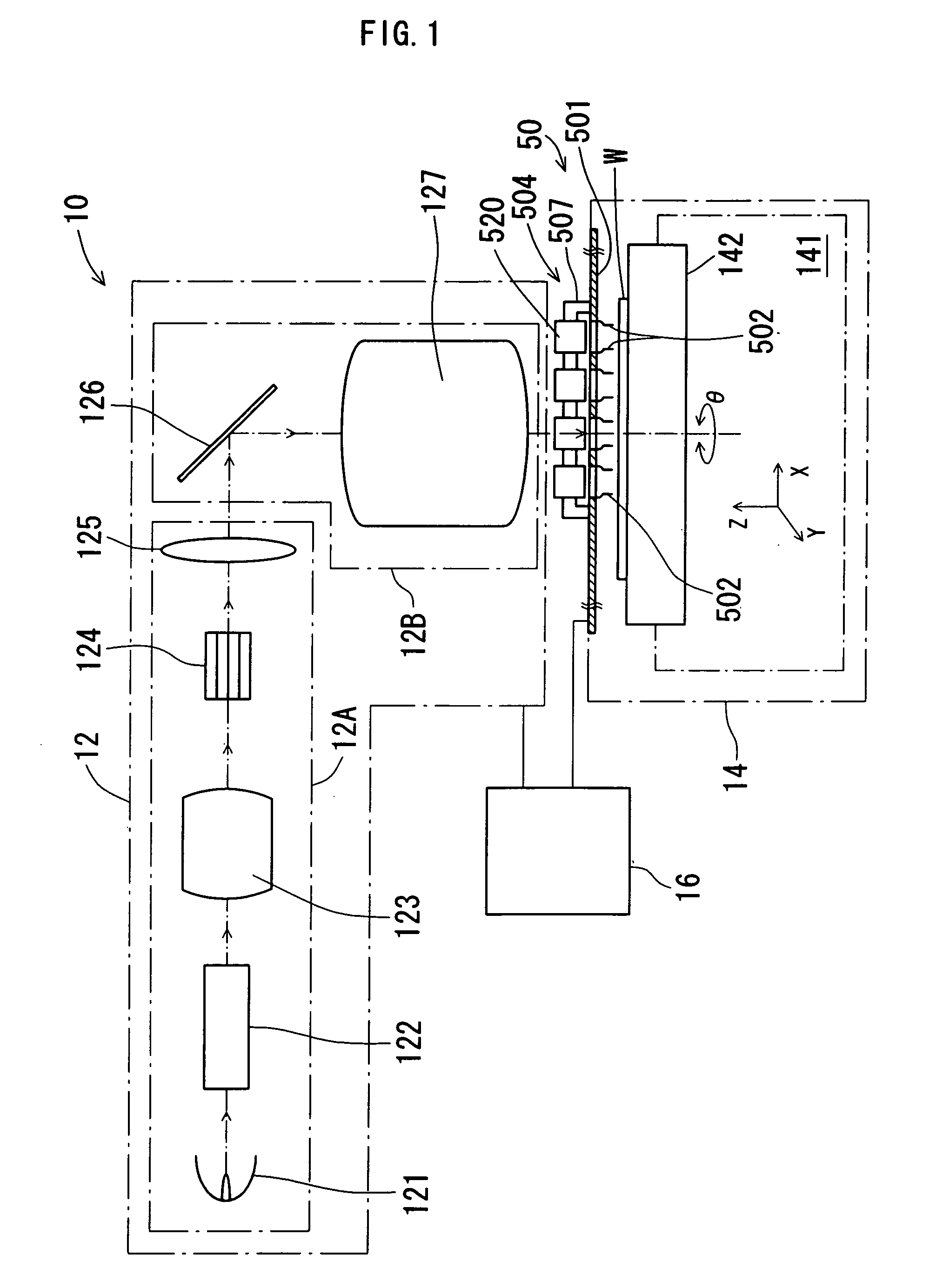
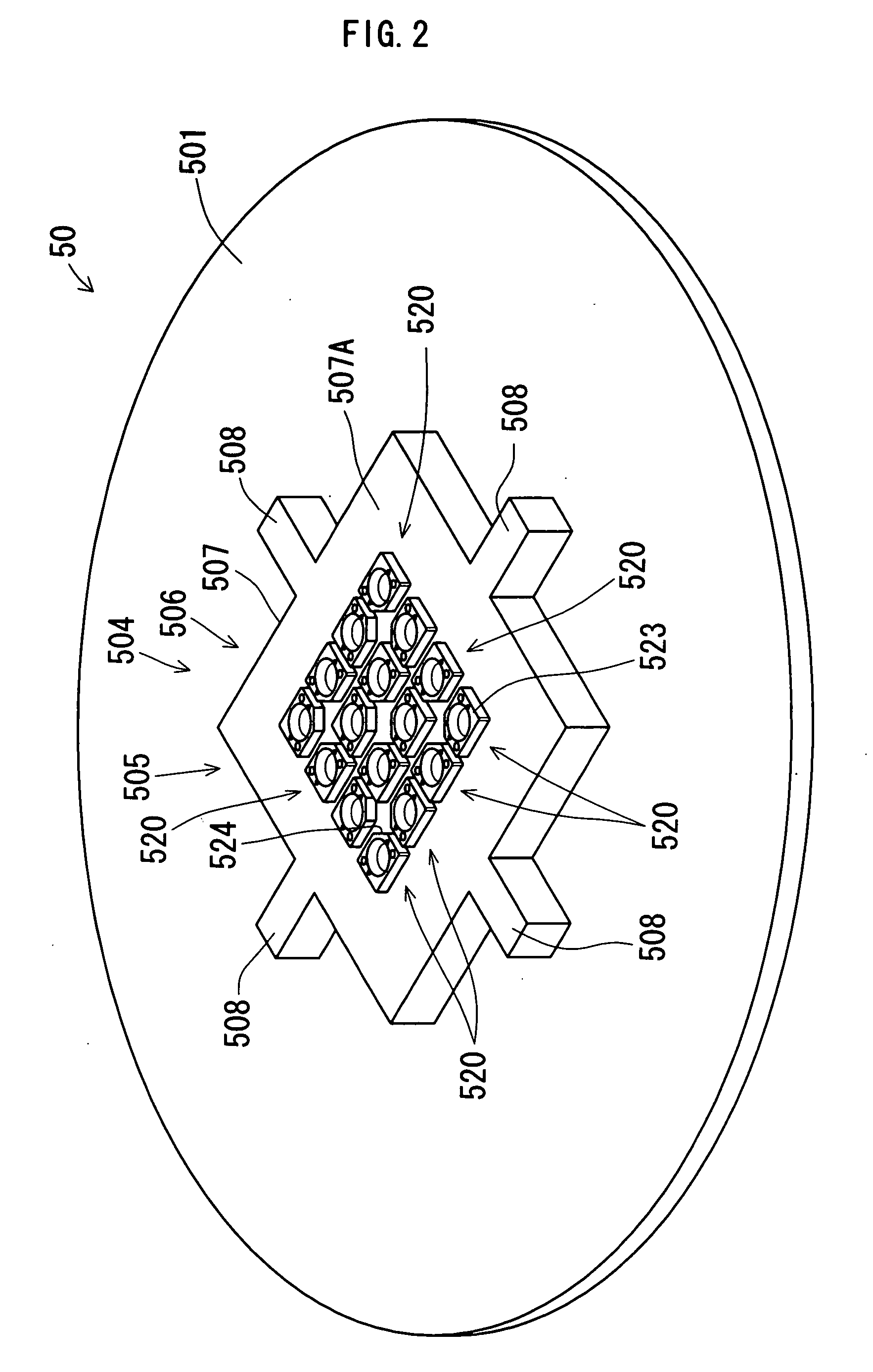
[0041]Hereinafter, embodiments of the present invention will be described with reference to the accompanying drawings. FIG. 1 to FIG. 8 show embodiments of an optical unit device, an optical unit, and an inspection apparatus for an image pickup device, of which FIG. 1 is a schematic configuration view of the inspection apparatus for an image pickup device. An inspection apparatus 10 for an image pickup device of the embodiment includes a light irradiator 12, a prober 14, a tester 16, and an optical inspection unit device 50.

[0042]In the present embodiment, the light irradiator 12 is a light irradiating means used in, for example, an inspection of photoelectric conversion characteristics of a solid-state image pickup device such as a CCD or a CMOS, for irradiating light onto a light receiving surface of the solid-state image pickup device and has a parallel light generating portion 12A and an irradiating introductory portion 12B. In the present embodiment, the parallel light generati...


PUM

PropertyMeasurementUnit
diameter×barrel lengthaaaaaaaaaa
photoelectric conversionaaaaaaaaaa
optical axisaaaaaaaaaa

Abstract

A probe card is equipped with a plurality of openings that transmit light to an image pickup device. An optical inspection unit that emits a test light through the plurality of openings of the probe card while being arranged in opposition to a light receiving portion of the image pickup device, a holding means that simultaneously positions and holds a plurality of optical inspection units, and an individual adjustment means that makes a converting adjustment carried out, for light from a light irradiator corresponding to the image pickup device, so as to match the same with specifications of the image pickup device be individually carried out for each optical inspection unit are provided. By replacing or adjusting each optical inspection unit while making the same attachable and detachable, an optical axis adjustment can be easily carried out, and the cost can be reduced.

Description

BACKGROUND OF THE INVENTION[0001]1. Field of the Invention[0002]The present invention relates to an inspection unit device, an inspection apparatus, and an optical inspection unit for a solid-state image pickup device such as a CCD image sensor, a CMOS image sensor, or the like.[0003]2. Description of the Prior Art[0004]Recently, with the increase in the number of pixels owing to an improvement in integration density of a solid-state image pickup device (image sensor) such as a CCD (Charge Coupled Device), a CMOS (Complementary Metal Oxide Semiconductor), or the like, the angle (angle of incidence or angle of view) of light made incident into the image sensor has increased. For this reason, a difference in quantity of light made incident into photodiodes occurs between the center part and peripheral part of the solid-state image pickup device, and shading for which the peripheral part is darkened increases. As a method for coping with the phenomenon, a pupil correction to secure lig...

Claims


Application Information

Patent Timeline
Patent Type & Authority Applications(United States)
IPC IPC(8): G01N21/00
CPCG01N21/84
Inventor YATSUGAKE, YASUOTANIGUCHI, YOSHITSUGU
Owner OYO ELECTRIC
Why Eureka
Try Eureka