
Low power Q-switched solid-state lasers

a solid-state laser, low-power technology, applied in the direction of laser details, laser monitoring arrangements, instruments, etc., can solve the problems of inability to achieve laser action in the resonator, excessively expensive and bulky prior-art q-switched pulsed lasers, limited commercial and industrial applications, etc., to achieve low cost and high volume

Inactive Publication Date: 2007-11-22
COHERENT INC
View PDF8 Cites 61 Cited by
  • Summary
  • Abstract
  • Description
  • Claims
  • Application Information

AI Technical Summary

Benefits of technology

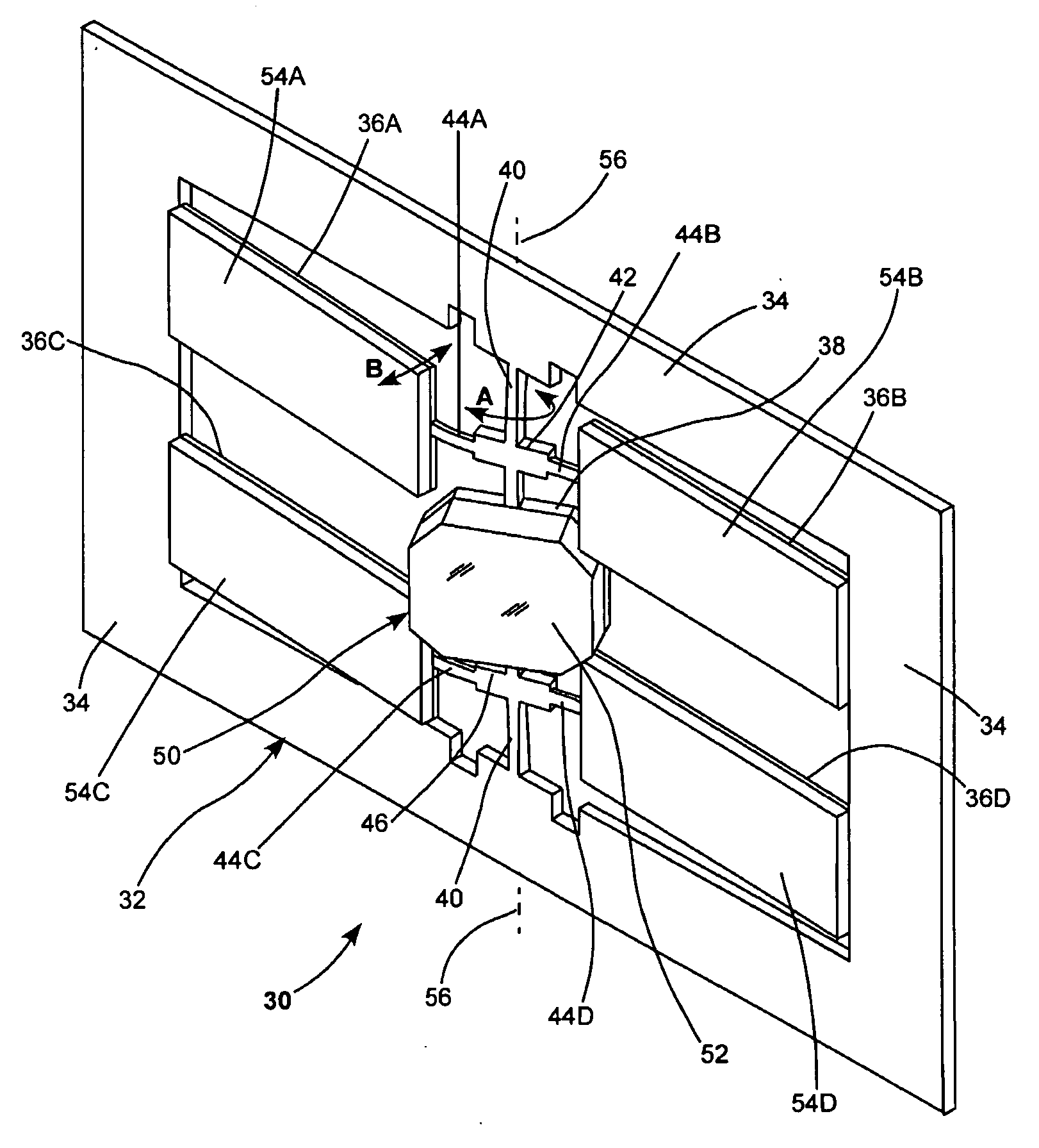
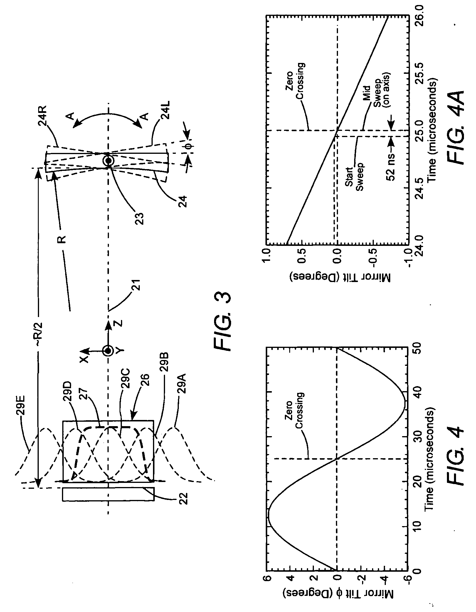
The present invention provides a laser that does not use an acousto-optical Q-switch. The laser includes a resonator with a mirror that is periodically tilted to sweep the resonator mode through the gain-medium in the resonator. This creates an excited volume where pump-light can optically pump the gain-medium. The tilting of the mirror can be controlled to generate pulses at regular intervals or to prevent pulses from being generated. The scanning of the mirror is achieved using a MEMS scanner that is cost-effective and can be manufactured in high volume. The technical effects of this invention include improved laser performance and reduced pulsed Q-switch noise.

Problems solved by technology

In a common mode of operation, the optical element, having the RF potential applied thereacross, has periodic refractive index differences induced therein, thereby behaving as a weak diffraction grating, and deflecting sufficient energy out of the resonator that lasing action in the resonator is not possible.
Such prior-art high-power Q-switched pulsed-lasers are sufficiently expensive and bulky that their use is limited to commercial and industrial applications.
Even though this teaching has been available to practitioners of the art for several years, it is not believed that a rotating faceted mirror or any rotating mirror has been incorporated as a Q-switch in any commercially available laser.
Further, each facet of such a rotating faceted device would need to be individually polished and optically coated, which is inconsistent with usual requirements for low-cost production.

Method used


Image

  • Low power Q-switched solid-state lasers
  • Low power Q-switched solid-state lasers
  • Low power Q-switched solid-state lasers

Examples


Embodiment Construction

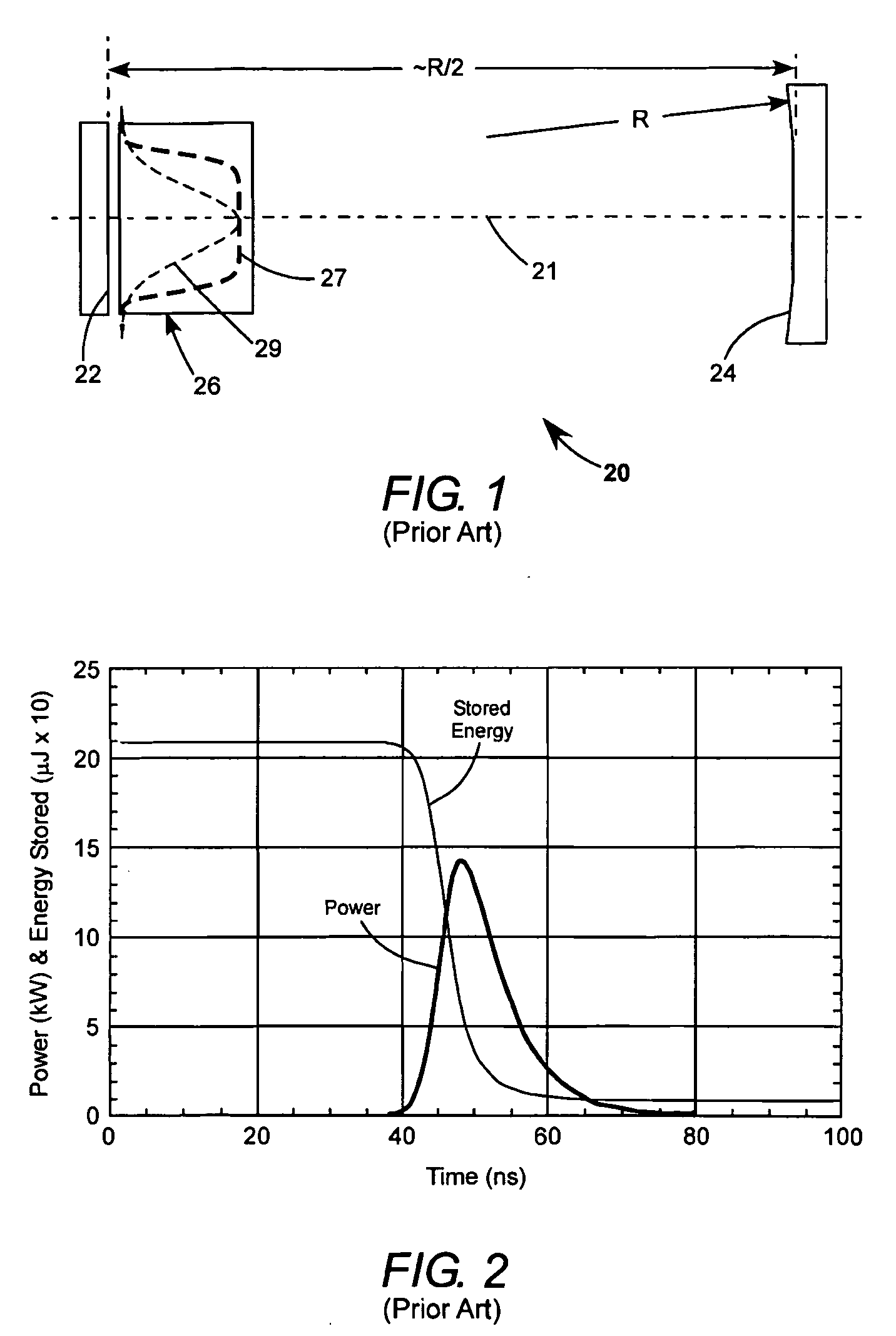
[0037]Referring now to the drawings, wherein like components are designated by like reference numerals, FIG. 1 schematically illustrates a hypothetical, basic, prior-art laser-resonator 20, suitable for Q-switched operation. Resonator 20 includes a plane, maximum-reflecting mirror 22, and a concave output-coupling mirror 24, with a gain-medium 26 located adjacent the plane mirror. The mirrors and the gain-medium are aligned on a longitudinal axis 21 of the resonator. A Q-switch is not shown in the resonator for simplicity of illustration. Resonator 20 is in a hemi-confocal arrangement, with concave mirror 24 having a radius of curvature (ROC) R and mirrors 24 and 22 being physically, axially spaced apart by a distance about equal to R / 2. The term “about”, as used in this instance, implies that the optimum physical spacing of the mirrors would depend on the optical length of the gain-medium, and the Q-switch (not shown).

[0038]Calculated pulse-delivery characteristics of an example of...


PUM


Abstract

In a miniature Q-switched, pulsed laser, having a two arm folded resonator, Q-switching is effected by rapidly and reciprocally tilting a resonator mirror of the laser about an axis perpendicular to the axis of the laser resonator. The angular excursion of the tilting and the frequency of the tilting are selected cooperative with dimensions of the resonator to maximize energy and symmetry of intensity distribution in Q-switched pulses delivered by the laser. Rapid reciprocal tilting of the mirror is accomplished using a piezoelectrically-driven, MEMS scanner operated in a resonant mode.

Description

TECHNICAL FIELD OF THE INVENTION[0001]The present invention relates in general to Q-switched pulsed lasers. The invention relates in particular to Q-switched pulsed lasers in which Q-switching is accomplished by a scanning resonator mirror.DISCUSSION OF BACKGROUND ART[0002]Pulsed Q-switched lasers are used in a variety of laser machining operations including cutting, drilling, routing, and marking of hard materials. The Q-switching principle involves locating an optical switch in a laser resonator. When the optical switch is in a “closed” mode, lasing action in the resonator is delayed until a gain-medium of the resonator has been energized, usually by optical pumping, for a time sufficient that energy stored in the gain-medium is close to, or at, a maximum possible (saturated) value. When the switch is “opened”, lasing action builds up in the resonator and the stored energy is released as a pulse. If the gain-medium is continuously pumped, the optical switch can be closed and opene...

Claims


Application Information

Patent Timeline
Patent Type & Authority Applications(United States)
IPC IPC(8): H01S3/093H01S3/08
CPCG02B26/0833H01S3/0014H01S3/0804H01S3/123H01S3/0815H01S3/09415H01S3/08059G02B26/0858
Inventor SPINELLI, LUIS A.CAPRARA, ANDREAJERMAN, JOHN H.
Owner COHERENT INC
Learn More