

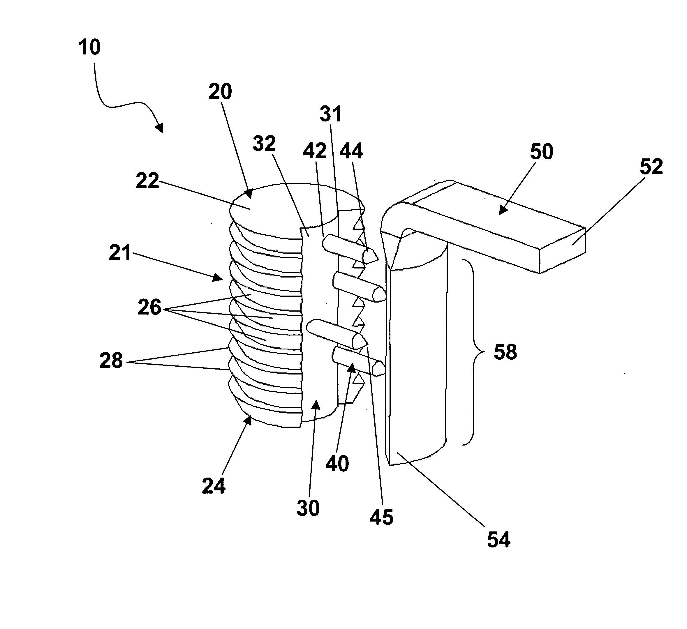
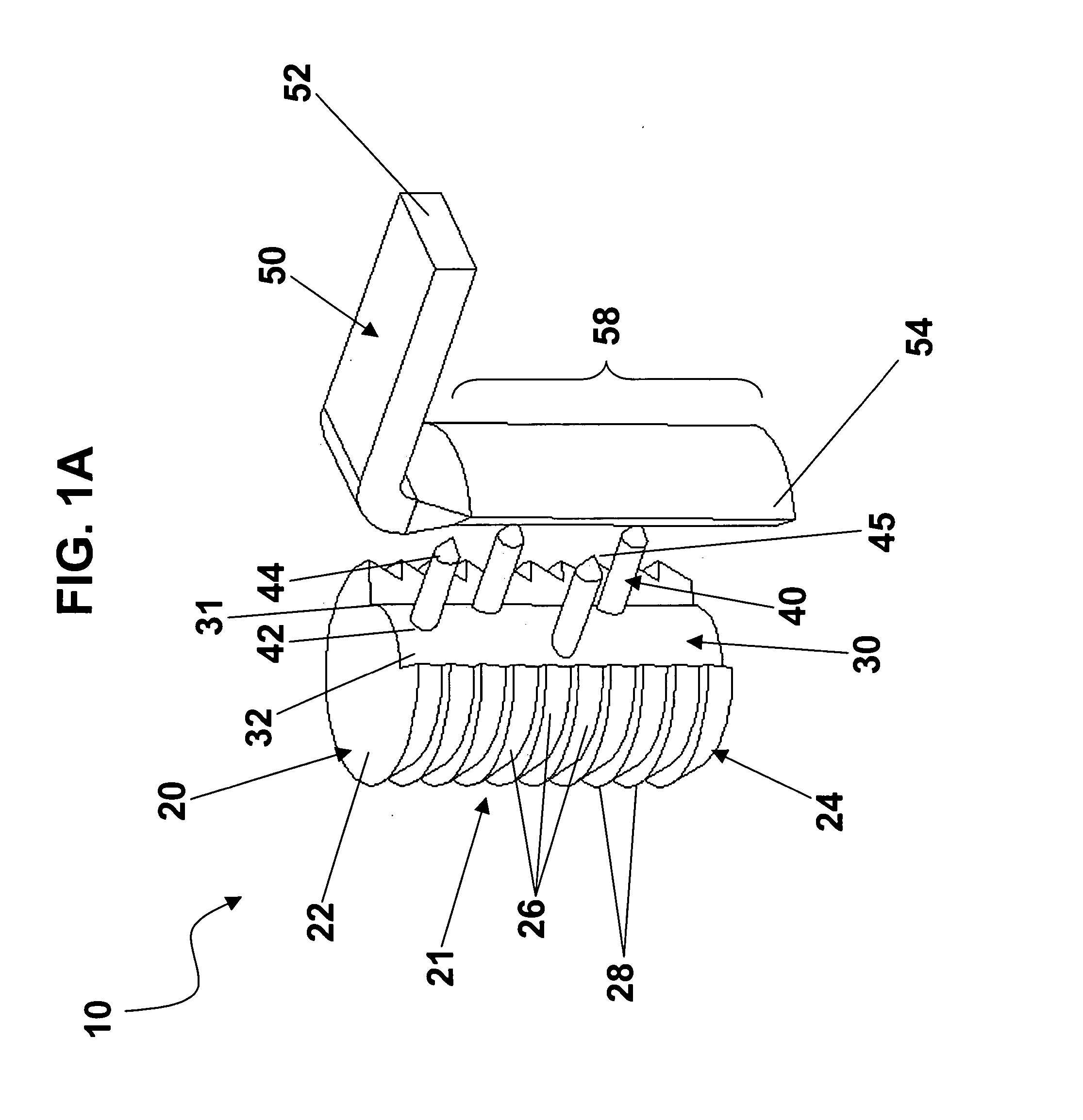
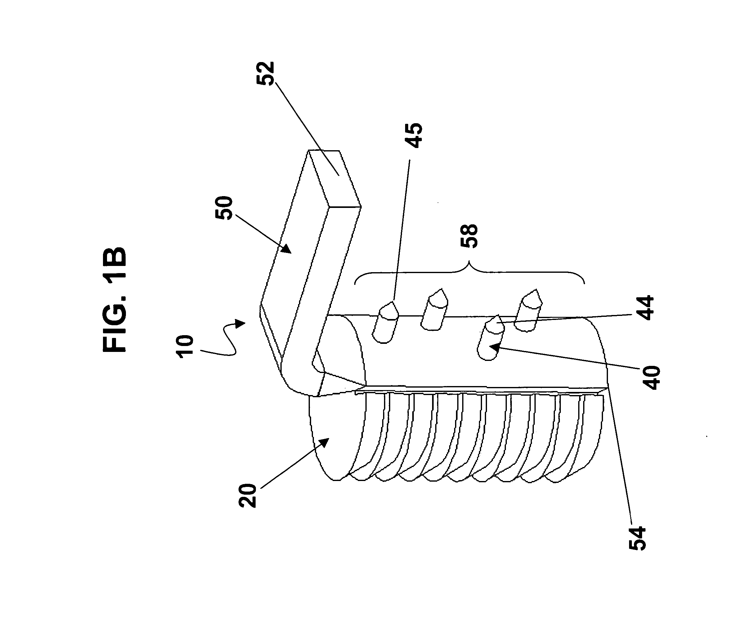
Bone anchoring device
a technology of bone anchoring and cable pullout, which is applied in the field of bone anchoring devices, can solve the problems of low pullout strength of the cable from the anchoring member, mechanical strength loss, and difficulty or inability to place a hole or eyel
- Summary
- Abstract
- Description
- Claims
- Application Information
AI Technical Summary
Problems solved by technology
Method used
Image

Examples
example 1
[0047] Forming cable / cover / anchor assemblies In this example, a general ultrasonic welding process was used to form strap, anchor, and cover assembly.
[0048] The cover was formed by compression molding (Model 2696, Carver, Inc., Wabash, Ind.). The material used to form the cover was 95 / 5 poly(lactide-co-glycolide) (95 / 5 PLGA) from PURAC (Gorinchem, The Netherlands), with an Inherent Viscosity (I.V.) of 2.33 dl / gm (measured in chloroform at 25° C. and a concentration of 0.1 gm / dl). The cover was cut to a square piece with the dimensions of 2×4.5 millimeter.
[0049] The cable was a three dimensional woven cable made using 95 / 5 poly(lactide-co-glycolide) (95 / 5 PLGA) fibers. The fibers are sold under the tradename PANACRYL, (Ethicon, Inc., Somerville, N.J.). The cable was 3D woven with 100 Denier fiber and a thickness of 1 millimeter and width of 2 millimeter at Fiber Concepts, Inc. (Conshohocken, Pa.).
[0050] The anchor was made using 95 / 5 poly(lactide-co-glycolide) by injection molding...
example 2
[0053] Surgical Procedure A patient is prepared for spinal fusion surgery in a conventional manner. The surgery will fuse one or more levels of the spinal column. The patient is anesthetized in a conventional manner. The tissue repair site is accessed by making an incision through the abdominal cavity and dissecting down to the spinal column. A sterile device of the present invention is prepared for implantation into the patient, the device having anchor members mounted to each end of the cable. The operative site is prepared to receive the anchor members of the repair device by dissecting through the ligamentous structure attached to the vertebral bodies of the spinal column that will be fused. A discectomy procedure is performed to remove the disc of the vertebral level to be fused and a bone graft is inserted into the discs space. A bore hole is drilled into the vertebral body above and below the disc space. The anchor bodies are then inserted into drilled bore holes in the adjoi...
PUM
 Abstract
Description
Claims
Application Information