Method of installing furnace walls of a boiler

a technology of furnace walls and boilers, which is applied in the direction of machines/engines, lighting and heating apparatus, water feed control, etc., can solve the problems of large restrictions on the establishment of the boiler frame, low operating efficiency of the construction process, etc., and achieve the effect of safe and efficient operation

Inactive Publication Date: 2007-11-29
MITSUBISHI HITACHIPOWER SYST LTD
View PDF4 Cites 13 Cited by
  • Summary
  • Abstract
  • Description
  • Claims
  • Application Information

AI Technical Summary

Benefits of technology

[0008]With the installation method of a boiler furnace wall according to the present invention, the furnace water wall panel with four faces that constitute the lower portion of boiler proper can be assembled at the more convenient location with safe and efficient operation. In addition to that, the installatio

Problems solved by technology

However, this construction process does not have high operating efficiency because of the dangerous operation in high altitude.
However, the method disclosed requires a large space in the boiler frame premise for as

Method used


Image

  • Method of installing furnace walls of a boiler
  • Method of installing furnace walls of a boiler
  • Method of installing furnace walls of a boiler

Examples


Embodiment Construction

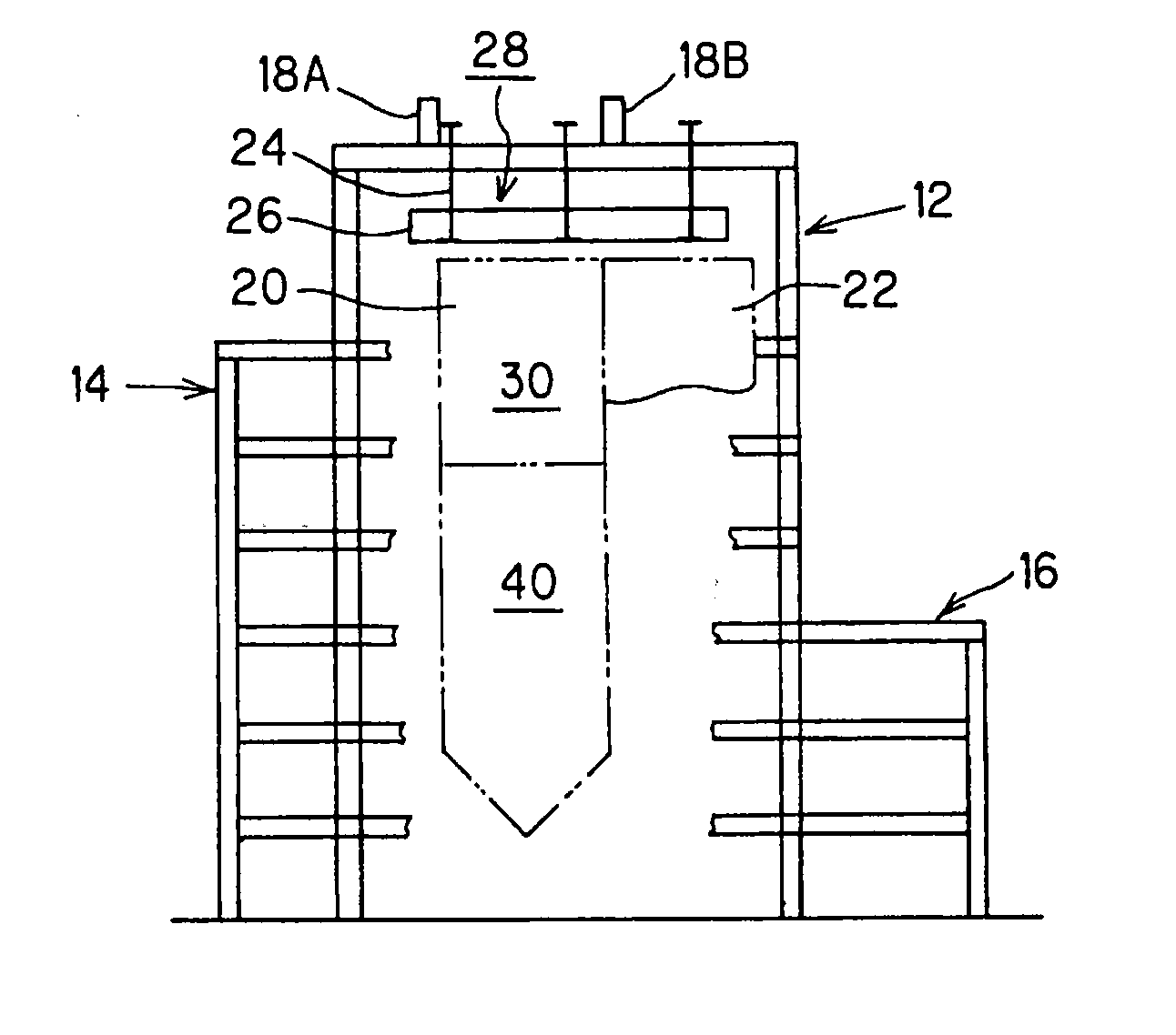
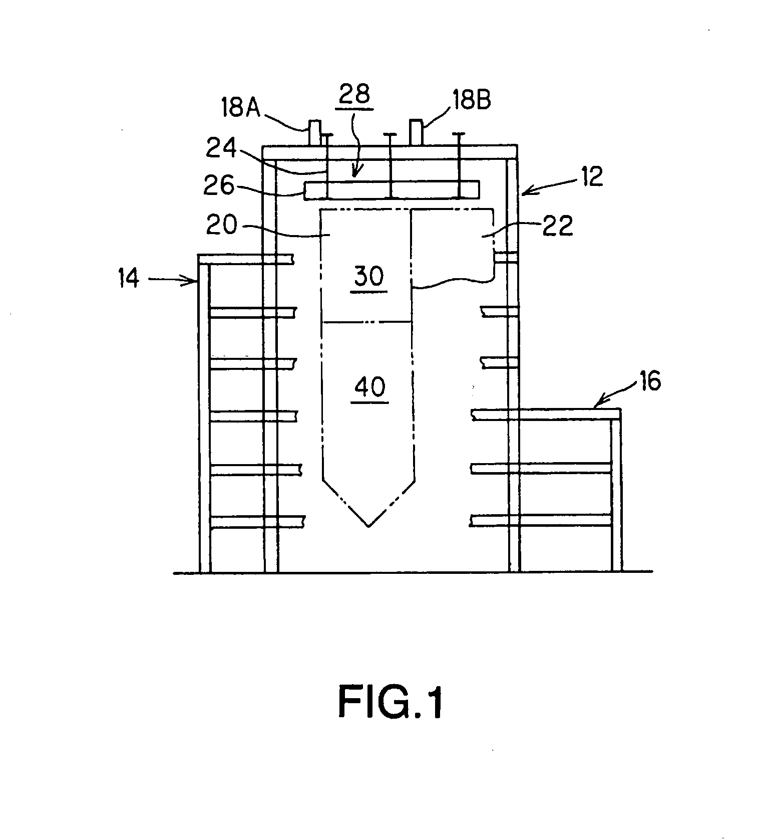
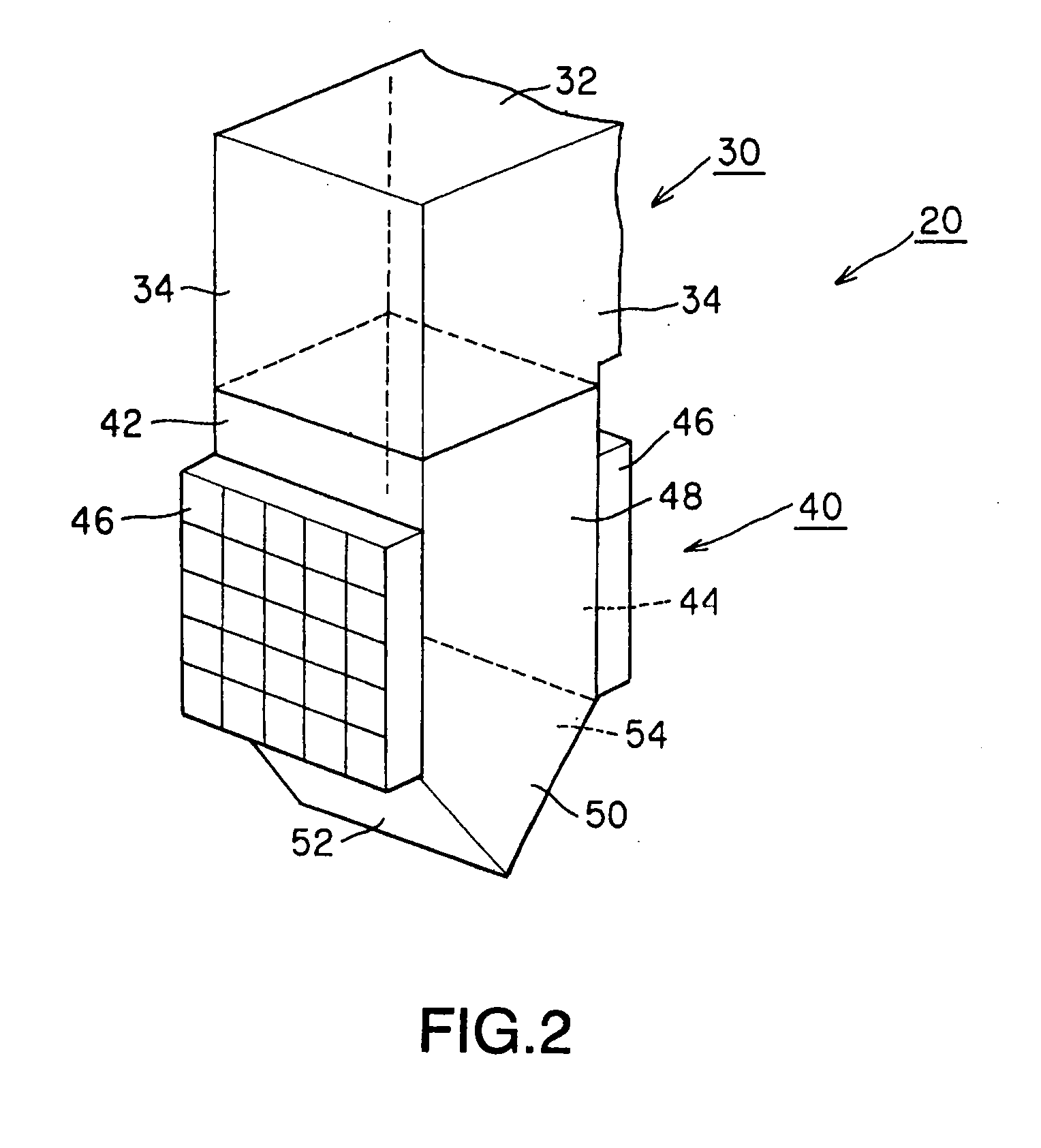
[0033]The method of installing the boiler furnace walls according to the present invention is a boiler furnace wall installation method with the upper portion of boiler proper and the lower portion of boiler proper that assembles the upper portion of boiler proper while it is suspended from the top girder module deployed in the boiler frame. At the same time, four faces of furnace water wall panels that constitute lower portions of boiler proper are assembled on the ground. Upon the completion of each face of the furnace water wall panels, this unit is brought in to the boiler frame premise and lifted toward the upper portion of boiler proper, and upper ends of each face of the furnace water wall panels are connected to lower ends of the upper portion of boiler proper. And the furnace water wall panel with four faces that constitute the lower portion of boiler proper can be assembled at the more convenient location with safe and efficient operation. In addition to that, the installa...


PUM

PropertyMeasurementUnit
Timeaaaaaaaaaa

Abstract

New and useful method of installing furnace walls for a boiler that does not require dedicated temporary lifting mechanism and reduces the installation work period significantly is disclosed. The method of installing furnace walls for a boiler configured with an upper portion of boiler proper 30 and a lower portion of boiler proper 40, temporally suspending two left and right face furnace water wall panels 48 among four furnace water wall panels, the upper portion of boiler proper is assembled while it is hanged from a top girder module 28 positioned on the top portion of a center portion in a boiler frame, a furnace rear wall 44 and a furnace front wall 42 among the furnace water wall panels are hanged sequentially, the temporally suspended two left and right face furnace water wall panels 48 are moved to designated positions, and the upper ends of the furnace water wall panels 48, 44 and 42 are connected with the lower end of the upper portion of boiler proper 30.

Description

FIELD OF THE INVENTION[0001]The present invention relates to a method of installing furnace walls of a boiler, more specifically a method of installing a furnace wall of a boiler suitable for constructing a large scale boiler such as one for a thermal power plan.DESCRIPTION OF THE RELATED ART[0002]FIG. 24 shows the exemplary side view of the schematic diagram of coal fired large scale boiler for a thermal power plant. A boiler 1 chiefly consists of a central portion 3 with a boiler furnace wall 2 and a convection pass wall 7, a front portion 5 with a coal bunker 4, and a rear portion 6 enclosing an air pre-heating device (not shown). The boiler furnace wall 2 and the convection pass wall 7 and others are suspended to a large beam 8 that is located on the top of a boiler frame, so as to release the thermal expansion during the burning operation.[0003]Accordingly, in a general construction process for the construction of the boiler furnace wall 2 and the convection pass wall 7, the la...

Claims


Application Information

Patent Timeline
IPC IPC(8): F22B37/24
CPCF22B37/001Y10T29/49387F22B37/244
Inventor KAWAGUCHI, SHIGEYOSHIHORINOUCHI, MOTOSHISAGAWA, SHINICHIMASUDA, YOSHITAKAIMAMURA, MASAKATSUMARIYAMA, TADAYOSHIKAWASHIMA, YASUAKI
Owner MITSUBISHI HITACHIPOWER SYST LTD
Why Eureka
Try Eureka