Method for Monitoring the Exhaust Gas Recirculation of an Internal Combustion Engine

a technology of internal combustion engine and exhaust gas, which is applied in the direction of machines/engines, electric control, instruments, etc., can solve the problems of large temperature stress on sensors exposed to exhaust gas flow, high cost, and malfunctions

Inactive Publication Date: 2007-11-29
ROBERT BOSCH GMBH
View PDF10 Cites 25 Cited by
  • Summary
  • Abstract
  • Description
  • Claims
  • Application Information

AI Technical Summary

Problems solved by technology

The necessary complexity additionally results in higher costs.
This indirect procedure is also relatively complex.
Further sensors are disadvantageous in this context; in particular, sensors that are exposed to the exhaust gas flow are subjected to large temperature stresses and malfunctions due to particle deposition.
If, however, the valve does not meter the expected exhaust gas mass flo

Method used


Image

  • Method for Monitoring the Exhaust Gas Recirculation of an Internal Combustion Engine
  • Method for Monitoring the Exhaust Gas Recirculation of an Internal Combustion Engine
  • Method for Monitoring the Exhaust Gas Recirculation of an Internal Combustion Engine

Examples


Embodiment Construction

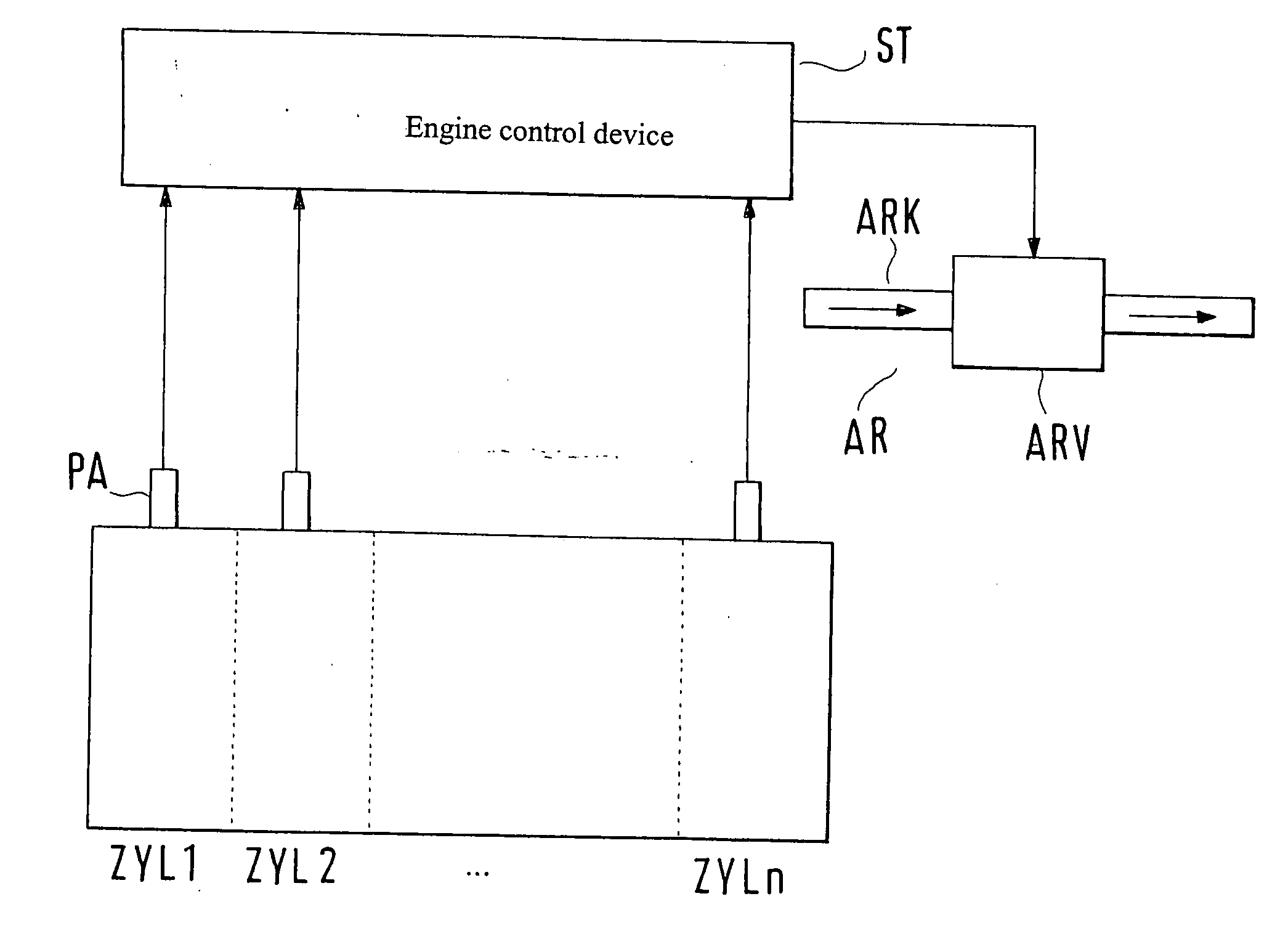
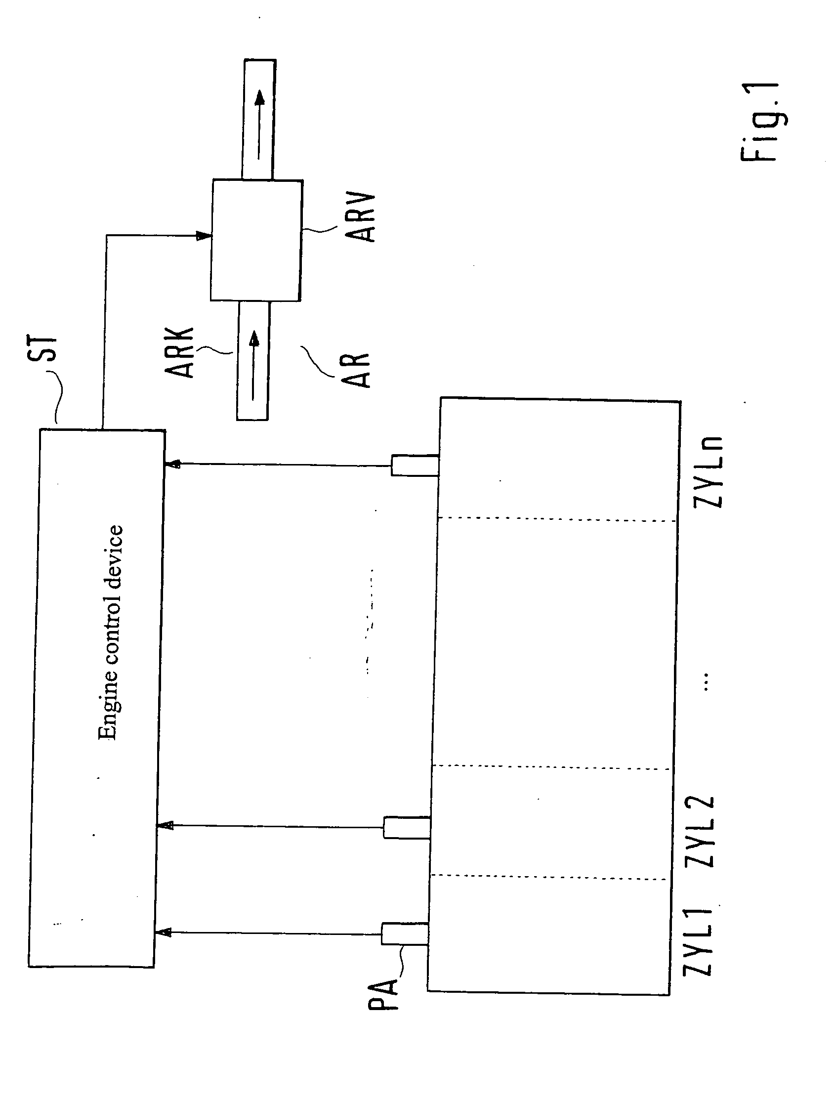
[0023]FIG. 1 schematically depicts a cylinder assemblage of an internal combustion engine having cylinders ZYL1, ZYL2, . . . ZYLn, which is connected from its output side (not depicted) to its input side (also not depicted) or intake region via an exhaust gas recirculation conduit ARK having an exhaust gas recirculation valve ARV arranged therein for exhaust gas recirculation AR. Usually one such exhaust gas recirculation AR is provided jointly for all cylinders ZYL1 . . . ZYLn, although an individual exhaust gas recirculation AR via respective exhaust gas recirculation conduits ARK is also conceivable. Cylinders ZYL1 . . . ZYLn are equipped with respective pressure transducers PA for the combustion chamber pressure or cylinder pressure, the signals of which transducers are conveyed to a control device ST for processing, evaluation, and optionally activation of exhaust gas recirculation valve ARV. Control device ST is a usual engine control device that performs a plurality of intern...


PUM


Abstract

A method for monitoring the exhaust gas recirculation of an internal combustion engine by pressure sensing, in which exhaust gas is recirculated from an outlet side of a combustion chamber assemblage via an exhaust gas recirculation conduit to an inlet side of the combustion chamber assemblage. Reliable monitoring of the exhaust gas recirculation with relatively little complexity is achieved by the fact that a pressure curve is sensed in at least one combustion chamber and a thermodynamic parameter is ascertained therefrom as an actual value; that a setpoint value of the parameter, which setpoint value takes into account the current operating point of the internal combustion engine, is made available, and a deviation between setpoint value and actual value is determined; and that a datum regarding the current exhaust gas recirculation state, as compared with its normal state, is obtained from the deviation.

Description

[0001] The present invention refers to a method for monitoring the exhaust gas recirculation of an internal combustion engine by pressure sensing, in which exhaust gas is recirculated from an outlet side of a combustion chamber assemblage via an exhaust gas recirculation conduit to an inlet side of the combustion chamber assemblage. BACKGROUND INFORMATION [0002] A method of this kind is described in DE 42 03 235 A1. With this known method, pressure values are successively sensed in an intake duct by way of a failure diagnosis apparatus of an exhaust gas recirculation control device, and the successive pressure value differences are accumulated. From the accumulated value, a failure diagnosis of the exhaust gas recirculation control device is performed by comparison with a predetermined value. With an indirect method of this kind, careful adaptations must be performed for each operating point of the internal combustion engine in order to prevent misdiagnoses. The necessary complexity...

Claims


Application Information

Patent Timeline
IPC IPC(8): F02M25/07F02B47/08G01M19/00F02M7/00F02D21/08F02D35/02F02D41/00F02D41/22G01M99/00
CPCF02D35/028F02D41/0052F02D35/023Y02T10/47F02M25/0702F02M26/49Y02T10/40
Inventor KASSNER, UWE
Owner ROBERT BOSCH GMBH
Why Eureka
Try Eureka