Electrolysis cell assembly

a technology of electrolysis cell and assembly, which is applied in the direction of manufacturing tools, electrical-based machining electrodes, machining electrodes, etc., can solve the problems of mass production, maintenance, repairability of these cells, and impracticality of maintenance, and the problem of reliably positioning and attaching the membranes within the cell to achieve sealed anode and cathode compartments remains a problem

Active Publication Date: 2007-11-29
CLARTECH HLDG
View PDF36 Cites 19 Cited by
  • Summary
  • Abstract
  • Description
  • Claims
  • Application Information

AI Technical Summary

Benefits of technology

[0010]The invention is directed to a compression sealable electrolysis cell assembly. The assembly has two insulating end pieces, each having a three concentric seats to position and seal the tubes where the central tube is sealed using an o-rings or compressible ridges in the end piece one or more holes parallel to the central axis of the concentric seats. The central seat accepts a ceramic membrane tube whose length that is less than the distance between the central seats of the two end pieces when the entire assembly is sealed. The two other seats accept two electrode tube one on either side of the ceramic membrane tube with one or both electrode tubes whose length is equal to the distance between its seats when they and the entire assembly are sealed. An electrical connector is a feature of these tubes. The assembly includes four ports which end in fittings to accept tubing. Two of the ports connect to the space between the outer...

Problems solved by technology

The mass production, maintainability, and repairability of these cells have suffered from the nature of the features of the assembly that results.
Diaphragm material is a particulate material within a bag such that construction required a skilled packer, and the sealing of the material into the system made them impractical to perform maintenance.
Reliably positioning and attaching the membranes within the cell to achieve sealed anode and cathode compartments remains a problem.
The use of soft and flexible polymeric ion permeable membranes are difficult to position and even more difficult to reliably seal.
The use of ion permeable ceramic membranes avoid the problems associated with the polymeric membranes due to their soft and flexible nature, but introduce other problems of providing a reliable seal as they are fragile and display a propensity to crack when a stress is applied to them.
The assembly has limitations in that the geometry must include a central rod electrode 6 which is threaded to compress the assembly.
This limit...

Method used


Image

  • Electrolysis cell assembly
  • Electrolysis cell assembly
  • Electrolysis cell assembly

Examples


Embodiment Construction

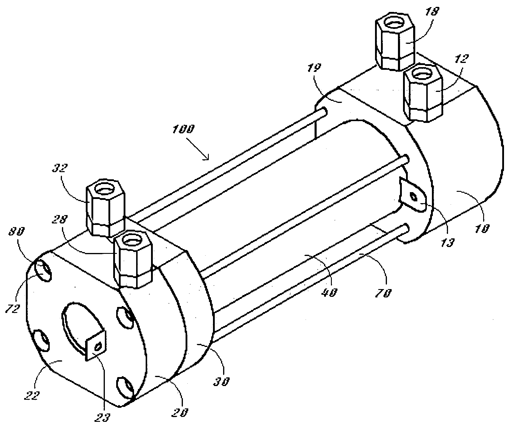
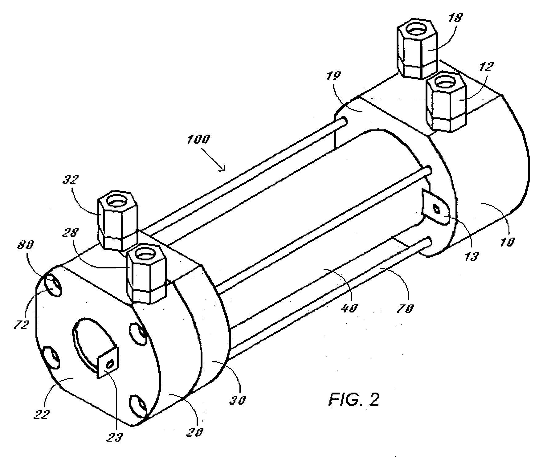
[0024]The present invention is directed to the construction of an optimized electrolysis cell assembly that can be mass produced and provides the ability to regularly deconstruct to maintain and repair. One embodiment is illustrated in FIG. 2 and FIG. 3 assembly 100, where a cylindrical electrode 60 is positioned within a cylindrical ion permeable ceramic membrane 50 which is positioned within a complimentary cylindrical electrode 40 by the use of two end pieces which are shown as a one section end cap 10 and a two section end cap 20, 30. The design of these end caps permit the orientation and sealing of the entire assembly 100. One end cap 10 features ports 11 and 17 for direction of the flow of electrolyte solutions through ports ending in fittings 12 an 18 into the compartments defined by the spaces between the electrodes and the membrane 45, 65 and out of the compartment through ports 31 and 27 ending in fittings 32 and 28, respectively, of the other end cap 20, 30, respectively...


PUM

PropertyMeasurementUnit
Fractionaaaaaaaaaa
Fractionaaaaaaaaaa
Angleaaaaaaaaaa

Abstract

A compression sealable electrolysis cell that is easily and reliably manufactured, maintained and repaired comprises two insulating end pieces which can position and seal two electrode tubes with electrical contacts separated by a ceramic membrane tube where fluid can be introduced at one end piece and removed at the other end piece in the spaces between the electrode tubes and the ceramic membrane tube. The design permits the compression of the entire assembly via the fixing of nuts on one or more threaded rods extending through both end pieces without the use of an adhesive or cement and without the imposition of torque or compressive stress on the ceramic membrane tube. The water or other fluid to be electrolyzed can be introduced tangentially to spaces between the electrode tubes and the ceramic membrane tube at a angle of 0 to 15 degrees to optimize flow and contact with the electrode tubes.

Description

FIELD OF THE INVENTION[0001]This invention relates to an electrolysis cell assembly of concentric cylindrical tubes.BACKGROUND OF THE INVENTION[0002]Electrolysis cells are useful for sanitizing water and for the generation of powerful biocides solutions from brine. Many types of electrolysis cell exist for these purposes. The basic feature of some of the most efficient cells is two concentrically disposed cylindrical electrodes with an ion permeable membrane separating the space between the two electrodes to define anode and cathode compartments. Typically an electrolyte solution is passed through the compartments separately or successively to generate the biocide and to sweep the accompanying gases that are generated through the system. The membrane permits the diffusion of electrolytes between the anode and cathode but retard the migration of electrolysis products at the anode and cathode from diffusing to each other reverting back to starting material or undesired side products.[...

Claims


Application Information

Patent Timeline
IPC IPC(8): C25C7/00C25B9/19
CPCC02F2201/003C25B13/02C25B11/02C25B9/08C25B9/19
Inventor DAVIS, JAMES E.VAN SCHAIK, MICHEL
Owner CLARTECH HLDG
Why Eureka
Try Eureka