Micro-electro-mechanical module

Active Publication Date: 2007-11-29
BELLUTECH LLC
View PDF8 Cites 55 Cited by
  • Summary
  • Abstract
  • Description
  • Claims
  • Application Information

AI Technical Summary

Benefits of technology

[0006] The present invention provides a MEMS module that contains an energy storage device whose discharge

Problems solved by technology

Furthermore, in many applications a batteryless operation is needed due to lack of battery replacement feasibility, or to meet stringent cost, form factor, and lifetime requirements.
However, in many situations, these environmental energy sources are not adequately available to power a sensor.
A common

Method used


Image

  • Micro-electro-mechanical module
  • Micro-electro-mechanical module
  • Micro-electro-mechanical module

Examples


Embodiment Construction

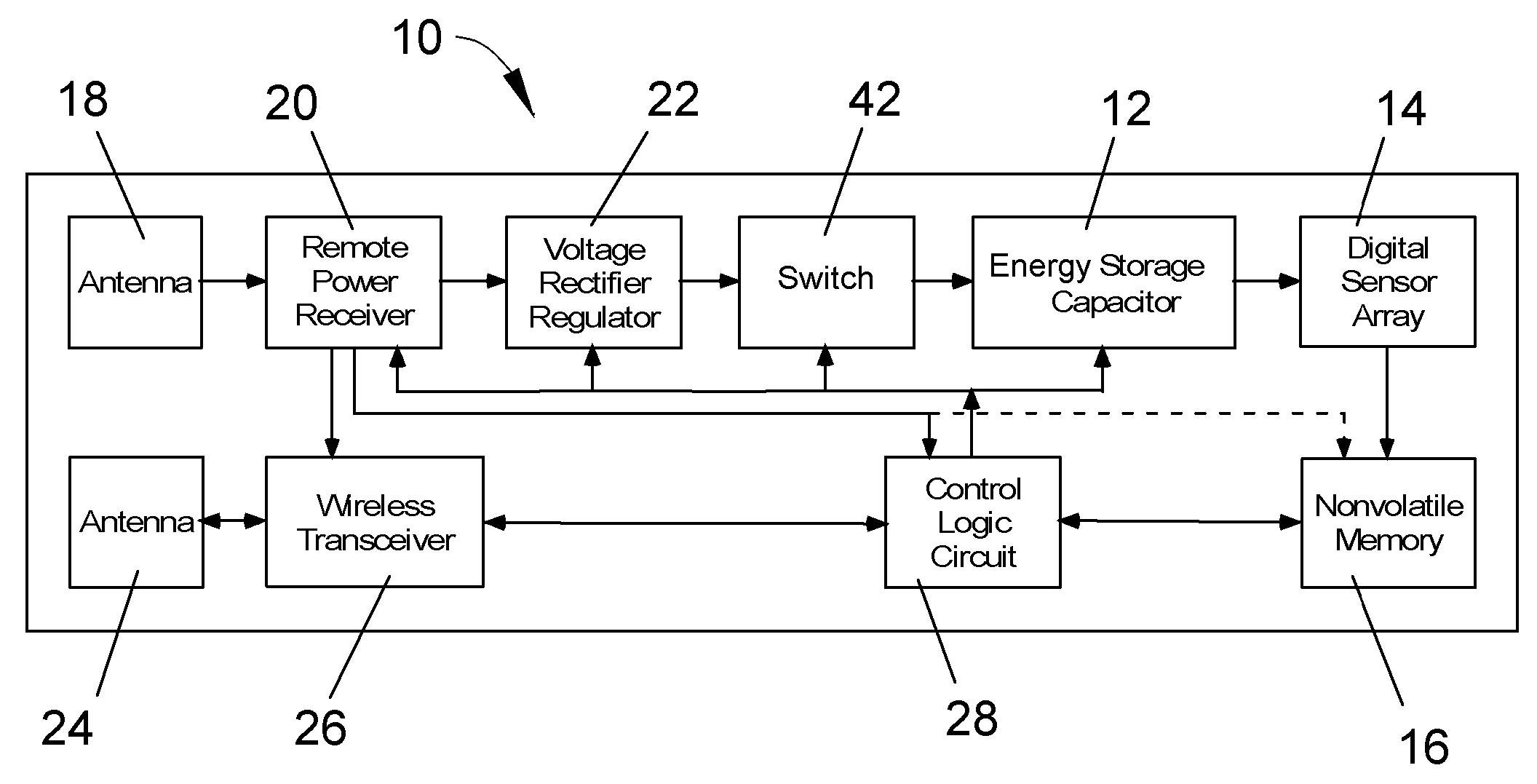
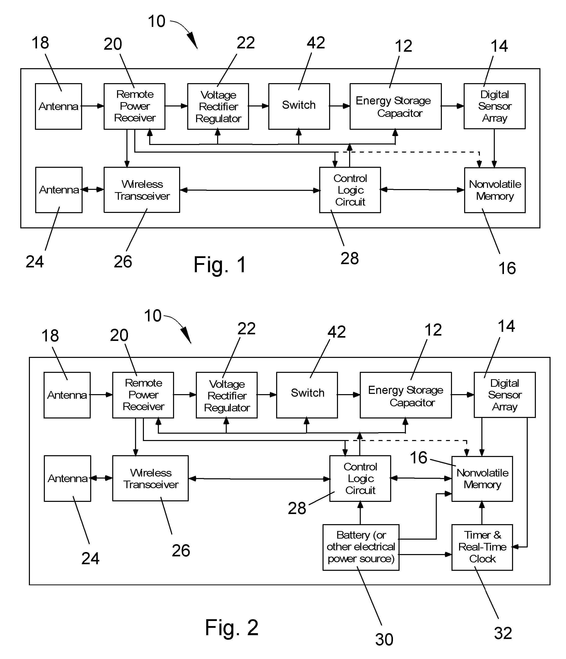
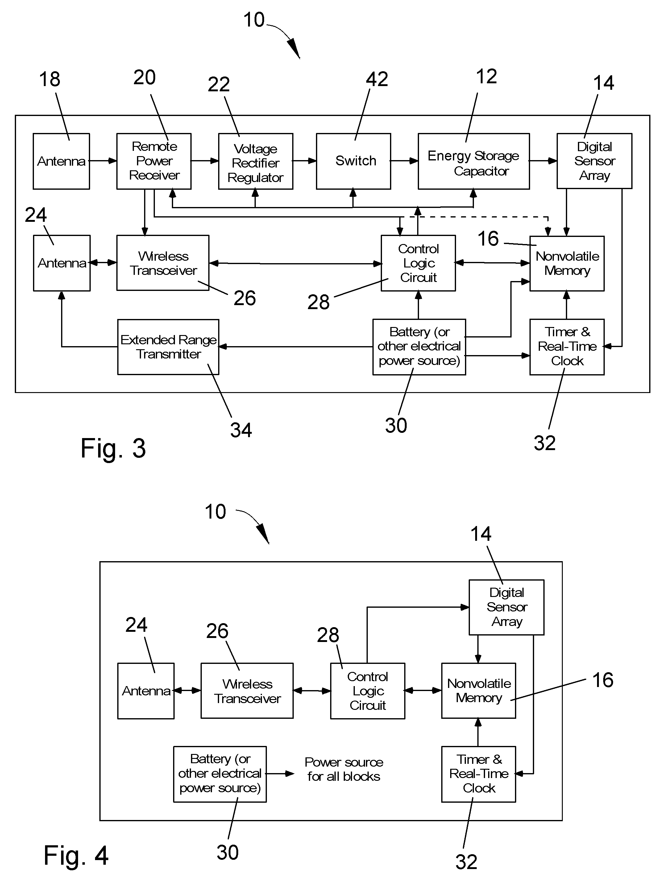
[0040] As will be evident from the following description, an object of this invention is to extend the life of a stored charge on a capacitor (or battery or other suitable energy storage device) by integrating the capacitor in a MEMS module containing one or more MEMS switches that physically isolate the capacitor from leaky electrical junctions. As used herein, the term MEMS (micro-electro-mechanical system) denotes a miniature device (generally on a scale of less than a millimeter) incorporating both electronic and mechanical functionalities and produced by micromachining techniques, such as bulk etching and surface thin-film etching.

[0041] Typically, charge storage capacitors are electrically isolated with electrical switches that leak current, such as at a p-n junction or gate. Though the charge leakage can be quite low, the inevitable effect is to discharge the capacitor over extended periods of time. Whereas such an effect is not detrimental to capacitors that can be periodic...


PUM


Abstract

A MEMS module that contains at least one integrated energy storage device whose discharge is minimized and controlled, so that power is available for system operation over longer periods of time. The MEMS module includes a device electrically coupled to the energy storage device for controlling charge transfers from the energy storage device while preventing charge leakage from the energy storage device. The controlling device includes a plurality of integrated MEMS switches that define open electrical paths that prevent charge leakage from the energy storage device through the MEMS switches, and are then operable to define closed electrical paths to allow charge transfers from the energy storage device, and preferably also allow charge transfers to the energy storage device, through the MEMS switches. The charge transfer can be utilized to power electronic circuits or store data in non-volatile digital memory.

Description

CROSS REFERENCE TO RELATED APPLICATIONS [0001] This application claims the benefit of U.S. Provisional Application No. 60 / 765,244, filed Feb. 4, 2006, the contents of which are incorporated herein by reference.BACKGROUND OF THE INVENTION [0002] The present invention generally relates to micro-electro-mechanical system (MEMS) and their fabrication. More particularly, this invention relates to a MEMS module capable of storing energy over an extended period of time by preventing charge leakage while allowing controlled charge transfers to and from an integrated energy storage device through the use of integrated MEMS switches. The MEMS switches can be adapted to be responsive to one or more external inputs, such as an environmental, chemical, or biological parameter, and the charge transfer through the switches can be utilized to power electronic circuits or store data in non-volatile digital memory, for example, to provide an output that correlates the charge transfer to an external i...

Claims


Application Information

Patent Timeline
IPC IPC(8): H01H51/22
CPCG01D21/00Y02B90/224G01P15/0888G01P15/135G01P15/18H01H1/0036H01H35/14H01H35/24H01H35/42H01H69/01H01H2001/0063H01H2037/008H01H2300/032Y04S20/14G01K5/62Y02B90/20
Inventor YAZDI, NAVID
Owner BELLUTECH LLC
Why Eureka
Try Eureka