Ultra low output impedance RF power amplifier for parallel excitation

Active Publication Date: 2009-05-21
GENERAL ELECTRIC CO
View PDF8 Cites 16 Cited by
  • Summary
  • Abstract
  • Description
  • Claims
  • Application Information

AI Technical Summary

Benefits of technology

[0008]In another aspect, an ultra-low output impedance Radio Frequency (RF) power amplifier for transmit coil decoupling in parallel excitation is provided. The ultra-low output impedance Radio Frequency (RF) amplifier

Problems solved by technology

However the current in each of the element coils is typ

Method used


Image

  • Ultra low output impedance RF power amplifier for parallel excitation
  • Ultra low output impedance RF power amplifier for parallel excitation
  • Ultra low output impedance RF power amplifier for parallel excitation

Examples


Example

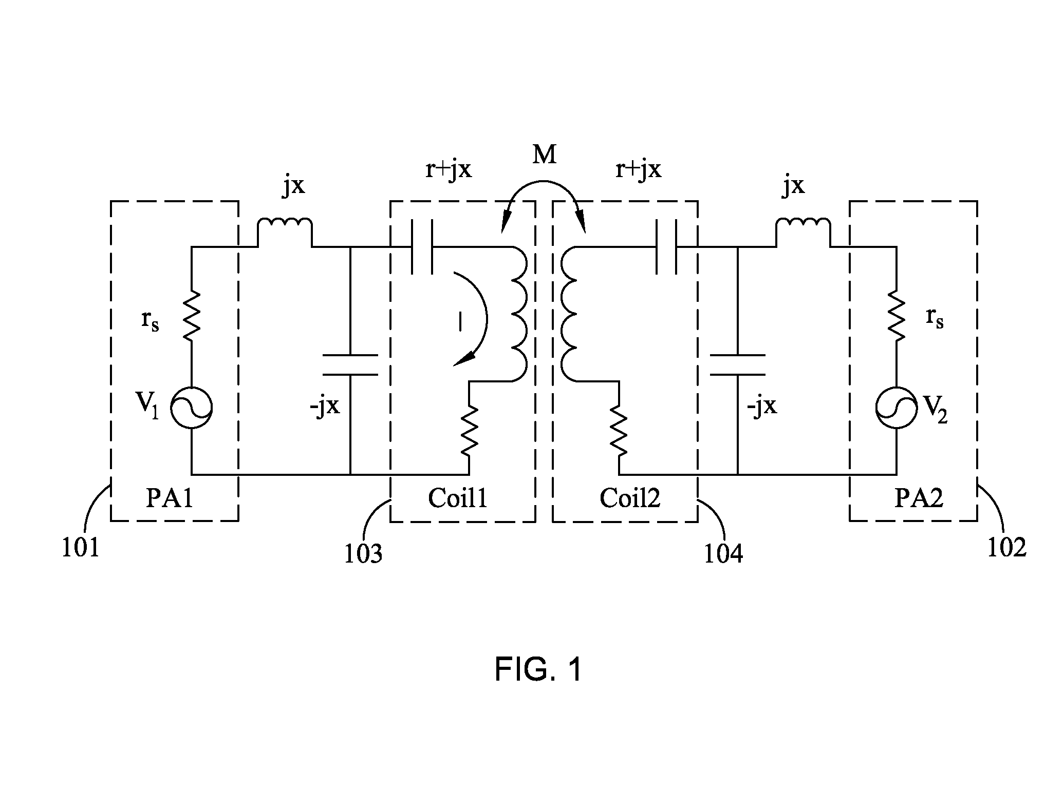
[0015]Referring to FIG. 1, it shows an equivalent circuit model of two identical coils 103, 104 driven by two independent RF power amplifiers 101, 102. Each power amplifier is modeled as a voltage source with a source resistance rs. The impedance of each coil without matching components is r+jx, and the inductive coupling between these two coils is captured by mutual inductance M. Representing a common configuration, the L-shaped matching network on each coil, which is consisted of a capacitor and an inductor, not only transforms the low impedance of the series resonant coil into a desired value (normally 50Q), but also amplifies the input current by x / r times. When both coils 103, 104 are driven by their corresponding amplifiers 101, 102, the current I running in coil 103 is consisted of two components, the desired one I(S) that is due to the controlling voltage V1 and the undesired (corruptive) one I(M) that is due to V2:

{I(S)=-jxV1rrS+ω2M2rS2 / (rrS+x2)+x2I(M)=-jxV2rrS+ω2M2rS2 / (rrS...


PUM


Abstract

An ultra low output impedance RF power amplifier for driving a multiple transmit coil Magnetic Resonance Imaging (MRI) system is described, comprising an output matching network with high power MOSFET operatively coupled to at least one transmit coil in the MRI system for a desired output power and impedance. This invention also describes a method for achieving decoupling using the RF power amplifier to drive at least one transmit coil.

Description

BACKGROUND[0001]The present invention relates to magnetic resonance systems, and more particularly to RF power amplifiers for parallel excitation in magnetic resonance systems.[0002]There has been very active development in the field of magnetic resonance (MR) where parallel RF transmission with multiple transmit elements is used to benefit various applications by improving spin excitation. In high field MR, inhomogeneity in the RF magnetic field caused by wave propagation and dielectric effect in particular, may be reduced by optimizing the amplitude and phase of the driving currents when conducting multi-port excitation on birdcage coils or transmit arrays consisted of individual coil elements. It is possible to further reduce the RF magnetic field in homogeneity effect by independently controlling the RF waveforms of individual transmit channels and leveraging the capacity of full fledged parallel RF transmission in accelerating multidimensional excitation and managing power depo...

Claims


Application Information

Patent Timeline
IPC IPC(8): G01R33/28
CPCG01R33/3614G01R33/3415
Inventor CHU, XULIU, YUNFENGZHU, YUDONG
Owner GENERAL ELECTRIC CO
Why Eureka
Try Eureka