Power limiting system for multiple electric motors

a technology of power limiting system and electric motor, which is applied in the direction of multiple dynamo-motor starters, motor/generator/converter stoppers, process and machine control, etc., can solve the problems of electrochemical cells being subjected to voltage collapse under high load conditions, electrical power may be significantly lower, overload problems, etc., to prevent any collapse, maximize power delivered from the generating source, and high friction

Active Publication Date: 2010-10-07
DEERE & CO
View PDF8 Cites 14 Cited by
  • Summary
  • Abstract
  • Description
  • Claims
  • Application Information

AI Technical Summary

Benefits of technology

[0007]The present invention provides a power limiting system for operating multiple electric motors with power from a Lundell alternator, battery, or other electric power generating component without losing functionality during start up, while encountering high friction, or during high loads. The power limiting system operates multiple electric motors while maintaining bus voltage above a specified threshold, and provides adequate power to the motors without brownouts. Power delivered from the generating source is maximized

Problems solved by technology

As a result, if current demand by the electric motors is very high, approaching or exceeding the capacity of the power generating component, the electrical power may be significantly lower due to a sharp voltage drop.
Once the voltage drops too far, it can be insufficient to power other electrical functions on the machine, resulting in a condition commonly referred to as “brownout.” Other power generating devices such as permanent magnet alternators, electrochemical batteries, DC machines, and others suffer from overload problems of a type similar to the above.
For example, electrochemical cells will undergo voltage collapse under high load conditions, particularly when the battery is highly discharged.
During start up, there is a large difference between actual reel speed and the set point, resulting in a proportional gain term that requires high current.
The high current demand, especially during start-up of multiple electric motors that turn cutting reels, may exceed the capacity of the power generating component.
As a result, a brownout condition may

Method used


Image

  • Power limiting system for multiple electric motors
  • Power limiting system for multiple electric motors
  • Power limiting system for multiple electric motors

Examples


Embodiment Construction

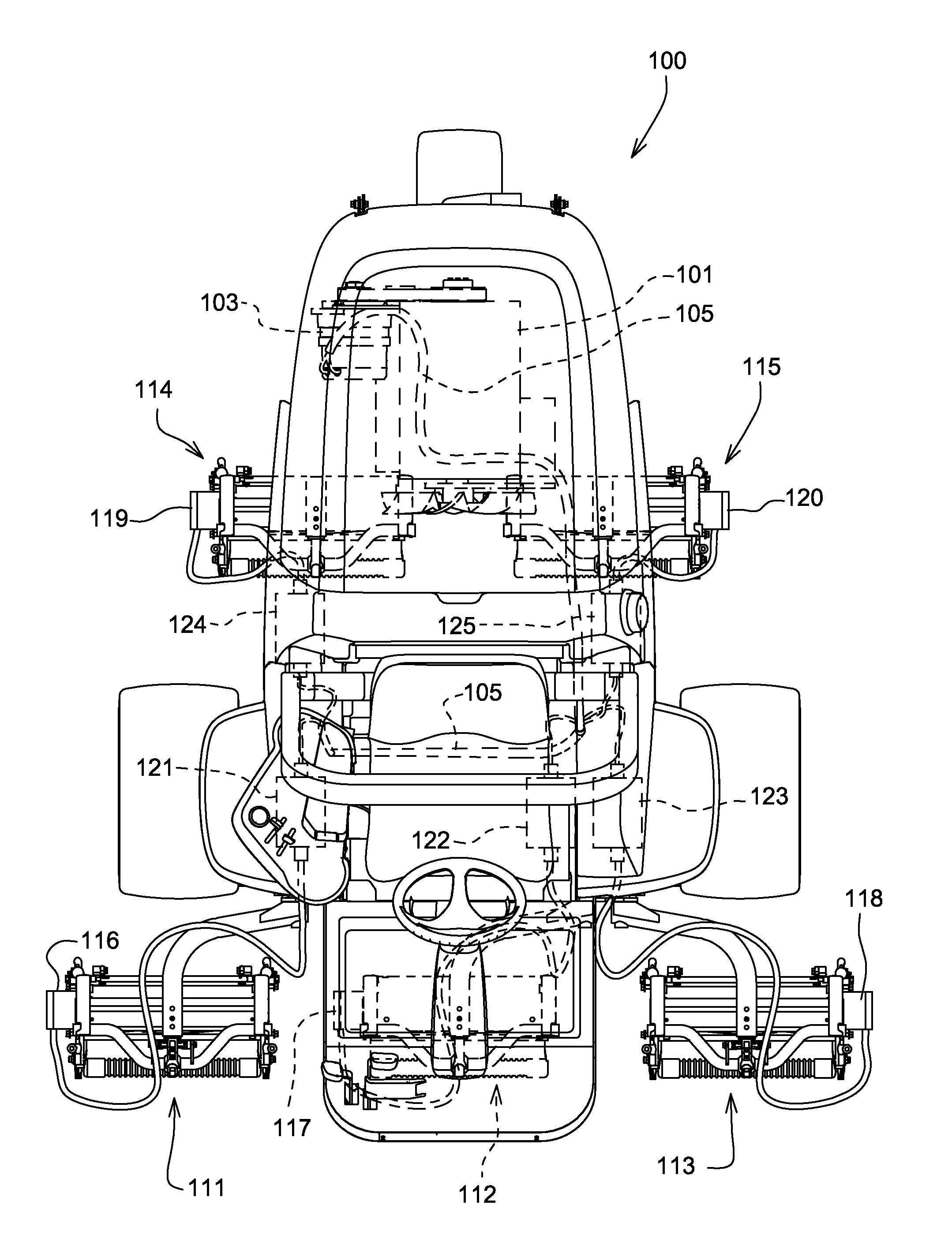
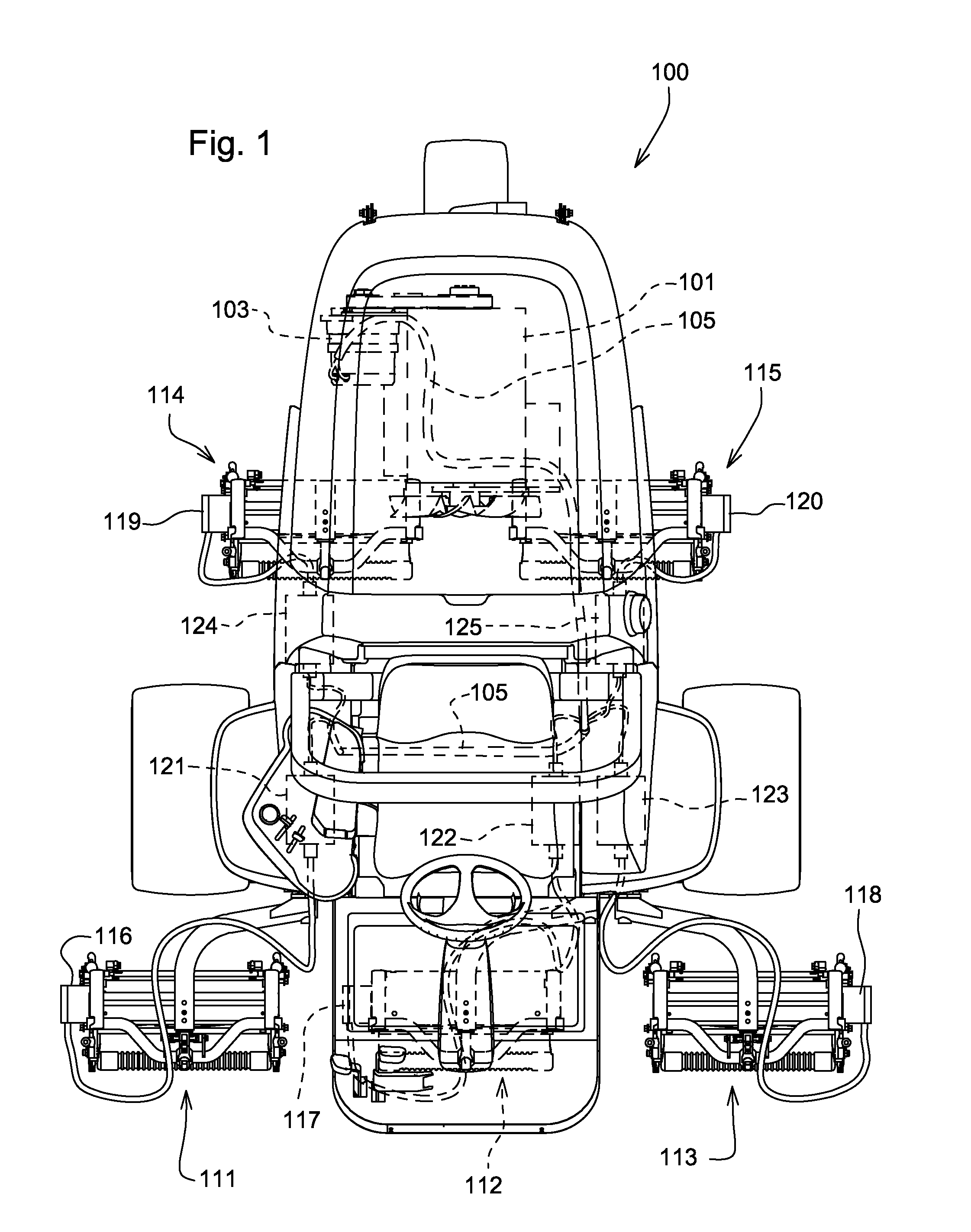
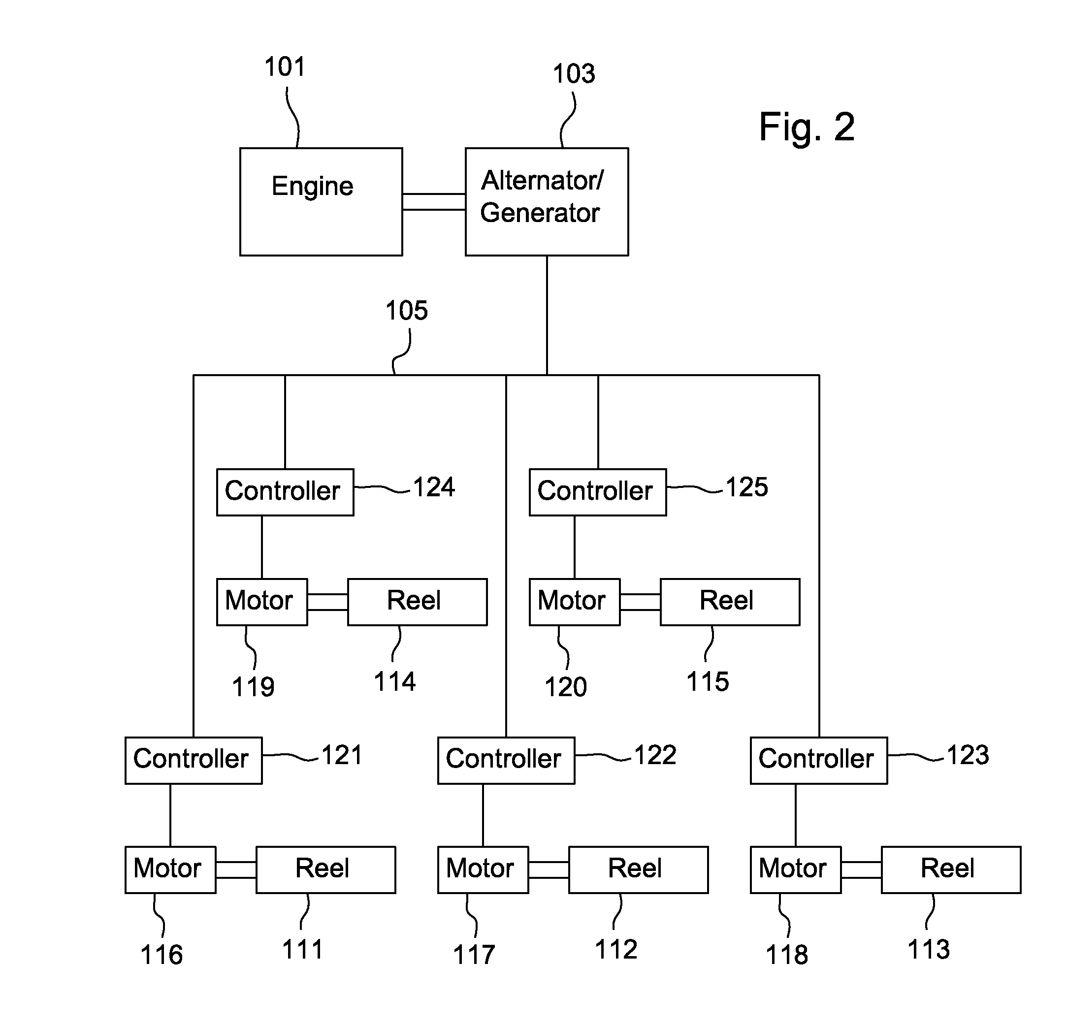
[0013]FIGS. 1 and 2 show embodiments of a power limiting system to maintain bus voltage for multiple electric motors. For example, the power limiting system may be used on a grass mowing machine, such as golf course fairway mower 100 with an internal combustion engine 101 or other power supply, that turns an electrical power generating source, such as a belt-driven Lundell alternator 103. The power limiting system also may be used in machines having electrical power from batteries or other electrical power generating components. The alternator, battery, or other electric power generating component may be electrically connected to electrical bus 105 to a plurality of electric motors 116-120, each electric motor provided with a motor controller 121-125 and rotating a reel cutting unit 111-115 or similar implement

[0014]The logic shown in the flow diagram of FIG. 3 may be programmed and implemented in software or hardware in the motor controllers 121-125. The logic of the power limiting...


PUM


Abstract

A power limiting system for multiple electric motors includes an electrical power generating component, such as an alternator, and a plurality of motor controllers connected to an electrical bus. Each motor controller compares the voltage on the bus to a specified minimum voltage and a specified maximum voltage, and reduces its electric power output if the voltage on the bus is less than the maximum voltage while continuing to operate the electric motors.

Description

FIELD OF THE INVENTION [0001]This invention relates to a power limiting system, and more specifically to a system for limiting electrical power for multiple electric motors that turn cutting reels or similar implements on a grass mowing machine.BACKGROUND OF THE INVENTION [0002]Electric motors are increasingly used on grass mowing machines for rotating cutting reels or other similar implements. On grass mowing machines, for example, power for multiple electric motors may be generated with a Lundell alternator that is belt driven by an internal combustion engine. A Lundell alternator can supply current under constant voltage conditions to an upper limit, depending on several factors including temperature. Above the upper limit, current can increase slightly, but voltage collapses sharply as the machine transforms from behaving as a voltage source to behaving as a current source. For example, an alternator that can supply 175 Amps at 48 Volts DC, can only support 35 Volts DC at 190 Am...

Claims


Application Information

Patent Timeline
IPC IPC(8): H02P7/00
CPCH02P29/02B60L11/123Y02T10/648Y02T10/6217Y02T10/7077A01D34/58B60L1/003B60L50/61Y02T10/62Y02T10/64Y02T10/70Y02T10/7072
Inventor GODBOLD, CLEMENT VANDENCROSS, PATRICK WILSON
Owner DEERE & CO
Why Eureka
Try Eureka