Integrated waveguide antenna and array

a waveguide antenna and array technology, applied in the direction of leaky waveguide antennas, linear waveguide fed arrays, antennas, etc., can solve the problems of high overall antenna cost, high conversion efficiency, and high cost of phase shifters, and achieve high conversion efficiency, high conversion efficiency, and high conversion efficiency

Active Publication Date: 2007-11-29
ORR PARTNERS I
View PDF33 Cites 46 Cited by
  • Summary
  • Abstract
  • Description
  • Claims
  • Application Information

AI Technical Summary

Benefits of technology

[0012]According to aspects of the invention, there is provided a novel radiating element which provide high conversion efficiency, while being small, simple, and inexpensive to manufacture.
[0013]According to aspects of the invention, there is provided a novel antenna having a radiating element which provides high conversion efficiency, while being small, simple and inexpensive to manufacture.
[0014]According to aspects of the invention, there is provided a novel antenna having an array of radiating elements which provide high conversion efficiency, while being small, simple, and inexpensive to manufacture.

Problems solved by technology

With micro-strip technology, antenna efficiency greatly diminishes as the size of the antenna increases.
However, phase shifters are costly and, particularly if the phased array incorporates many elements, the overall antenna cost can be quite high.
Also, phase shifters require separate, complex control circuitry, which translates into unreasonable cost and system complexity.
While that antenna is said to have a low profile—extending to a height of “only” 14 inches without the radome (radar dome)—its size may be acceptable for military applications, but not acceptable for consumer applications, e.g., for private automobiles.
Current mobile systems are expensive and complex.
In practical consumer products, size and cost are major factors, and providing a substantial reduction of size and cost is difficult.
In addition to the cost, the phase shifters of known systems inherently add loss to the respective systems (e.g., 3 dB losses or more), thus requiring a substantial increase in antenna size in order to compensate for the loss.
In a particular case, such as a DBS antenna system, the size might reach 4 feet by 4 feet, which is impractical for consumer applications.
Current antenna systems are relatively too large for commercial use, have problems with collection efficiency, and are priced in the thousands, or even tens of thousands of dollars, thereby being way beyond the reach of the average consumer.

Method used


Image

  • Integrated waveguide antenna and array
  • Integrated waveguide antenna and array
  • Integrated waveguide antenna and array

Examples


Embodiment Construction

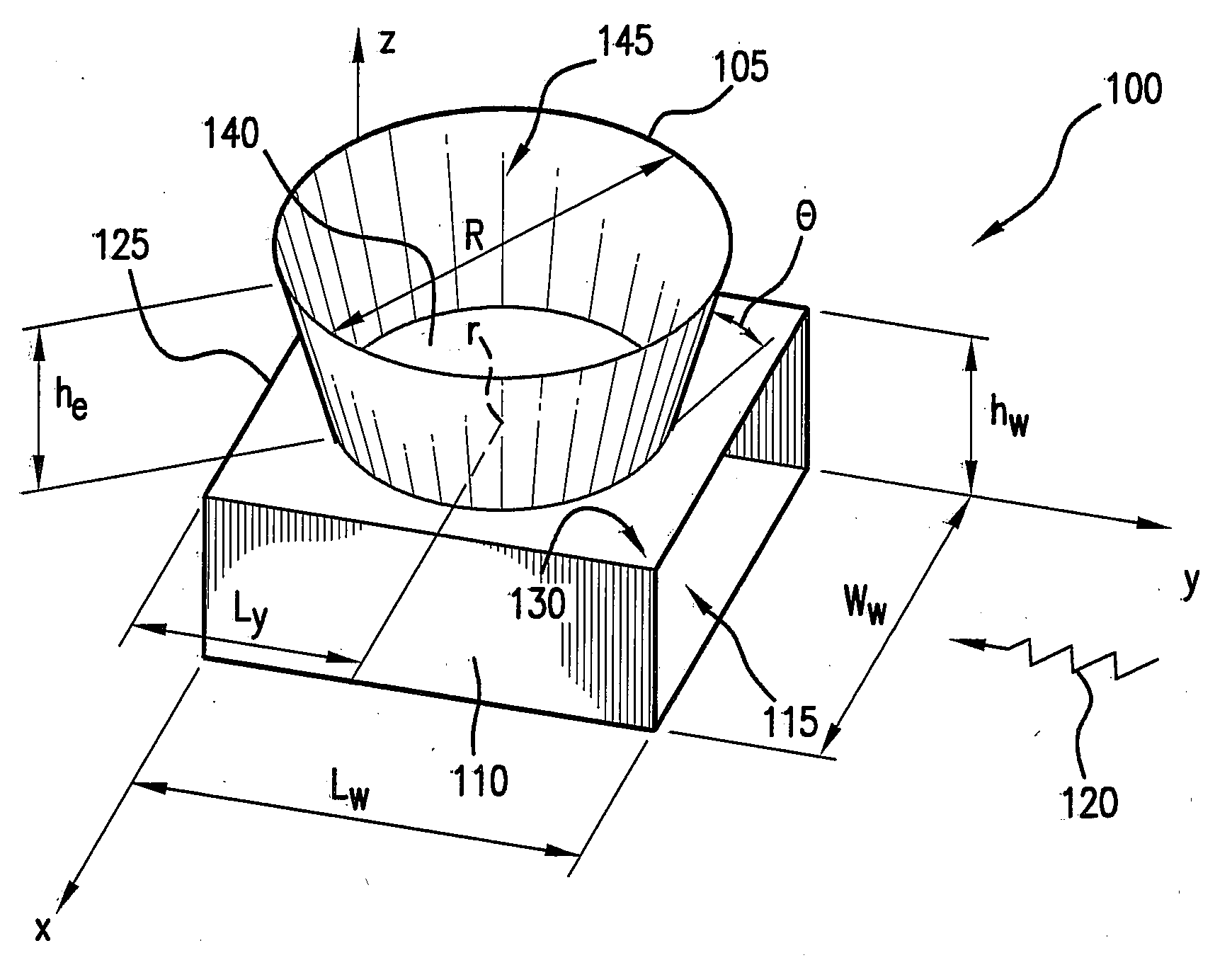
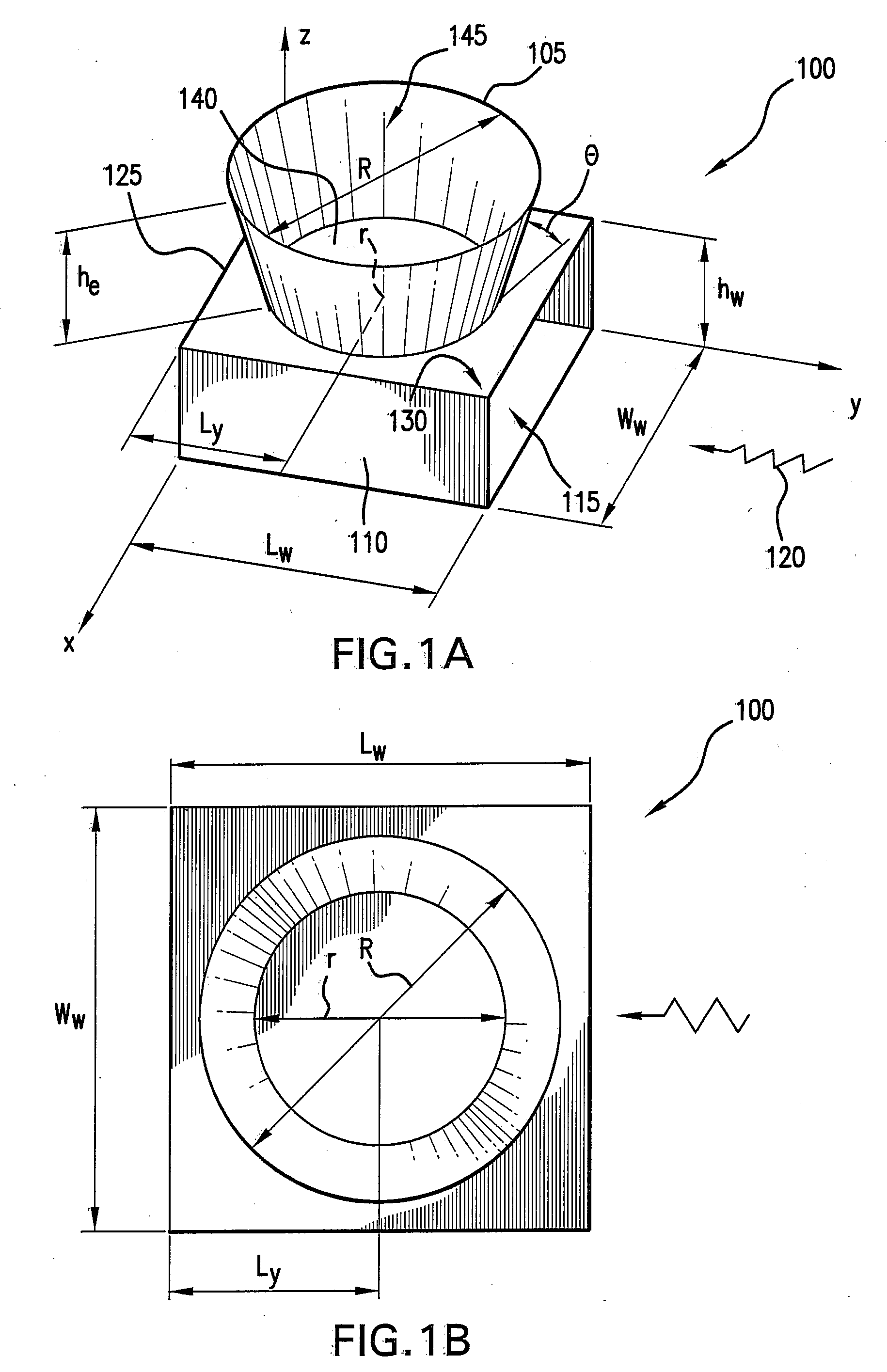
[0040]Various embodiments of the invention are generally directed to radiating elements and antenna structures and systems incorporating the radiating element. The various embodiments described herein may be used, for example, in connection with stationary and / or mobile platforms. Of course, the various antennas and techniques described herein may have other applications not specifically mentioned herein. Mobile applications may include, for example, mobile DBS or VSAT integrated into land, sea, or airborne vehicles. The various techniques may also be used for two-way communication and / or other receive-only applications.

[0041]According to an embodiment of the present invention, a radiating element is disclosed, which is used in single or in an array to form an antenna. The radiating structure may take on various shapes, selected according to the particular purpose and application in which the antenna will be used. The shape of the radiating element or the array of elements can be de...


PUM


Abstract

An antenna is provided. The antenna may include at least one open-ended structure extending from a surface of a waveguide. The open-ended structure may have a cross section of many different shapes. The walls of the structure may be movable. The antenna structure may be rotated. The antenna may incorporate a number of different wave feeds. The antenna may provide two-dimensional beam steering.

Description

CROSS-REFERENCE TO RELATED APPLICATIONS[0001]This Application is a continuation of and claims priority from U.S. Application, Ser. No. 60 / 808,187, filed May 24, 2006; U.S. Application, Ser. No. 60 / 859,667, filed Nov. 17, 2006; U.S. Application, Ser. No. 60 / 859,799, filed Nov. 17, 2006; and U.S. Application, Ser. No. 60 / 890,456, filed Feb. 16, 2007, the disclosure of all of which is incorporated herein by reference in its entirety.BACKGROUND[0002]1. Field of the Invention[0003]The general field of the invention relates to a unique electromagnetic building block which can be used for radiating and non-radiating electromagnetic devices. Embodiments of the invention relate generally to antenna structures and, more particularly, to antenna structure having a radiating element integrated to a waveguide, and to antenna having an array of radiating elements integrated to a waveguide.[0004]2. Related Arts[0005]Various antennas are known in the art for receiving and transmitting electromagnet...

Claims


Application Information

Patent Timeline
Patent Type & Authority Applications(United States)
IPC IPC(8): H01Q13/00
CPCH01Q3/22H01Q13/00H01Q13/0233H01Q21/064H01Q21/0012H01Q21/005H01Q21/0062H01Q13/22
Inventor HAZIZA, DEDI DAVID
Owner ORR PARTNERS I
Why Eureka
Try Eureka