Ink jet printing system for printing colored images on contact lenses

a technology of contact lenses and printing systems, applied in the direction of printing, optical elements, instruments, etc., can solve the problems of inconvenient printing, lack of consistency in the method, and difficulty in multiple color layering,

Inactive Publication Date: 2007-11-29
ALCON INC
View PDF0 Cites 13 Cited by
  • Summary
  • Abstract
  • Description
  • Claims
  • Application Information

AI Technical Summary

Benefits of technology

[0008] In another aspect of the invention, a printing apparatus for making colored contact lenses comprises: a securing means for holding a contact lens or a portion of a mold for making the contact lens; a printer head, wherein the printer head comprises one or more nozzles each of which is capable of jetting droplets of color liquid independent of each other under control of a computer system; a positioning means for precisely positioning the printer head at each of a plurality of predetermined positions, one at a time, on a surface of the contact lens or the mold portion under control of the computer system.

Problems solved by technology

There are several disadvantages associated with using cliché ink transfer printing to color contact lenses.
This method lacks consistency.
Further, multiple color layering is difficult and time consuming.
Further still, the design and printing process using this method is slow.
The set-up is painstakingly detailed and lengthy when more than one color is going to be printed on the lens using this method.
The difficulty and slowness of this printing method inhibits business strategies, making it difficult to offer consumers a chance to design and print their own contact lenses at the point of purchase.
These systems and methods in the prior art are not suitable for printing colored images with high quality on objects with curved surfaces to be printed, such as hemispherical contact lenses or molds for making contact lenses, especially in an industrial setting for high-throughput production of colored contact lenses.

Method used


Image

  • Ink jet printing system for printing colored images on contact lenses
  • Ink jet printing system for printing colored images on contact lenses
  • Ink jet printing system for printing colored images on contact lenses

Examples


example 1

[0087] This example provides method for making a colored contact lens by first printing a color image on a mold portion (male mold) defining the posterior surface of a contact lens.

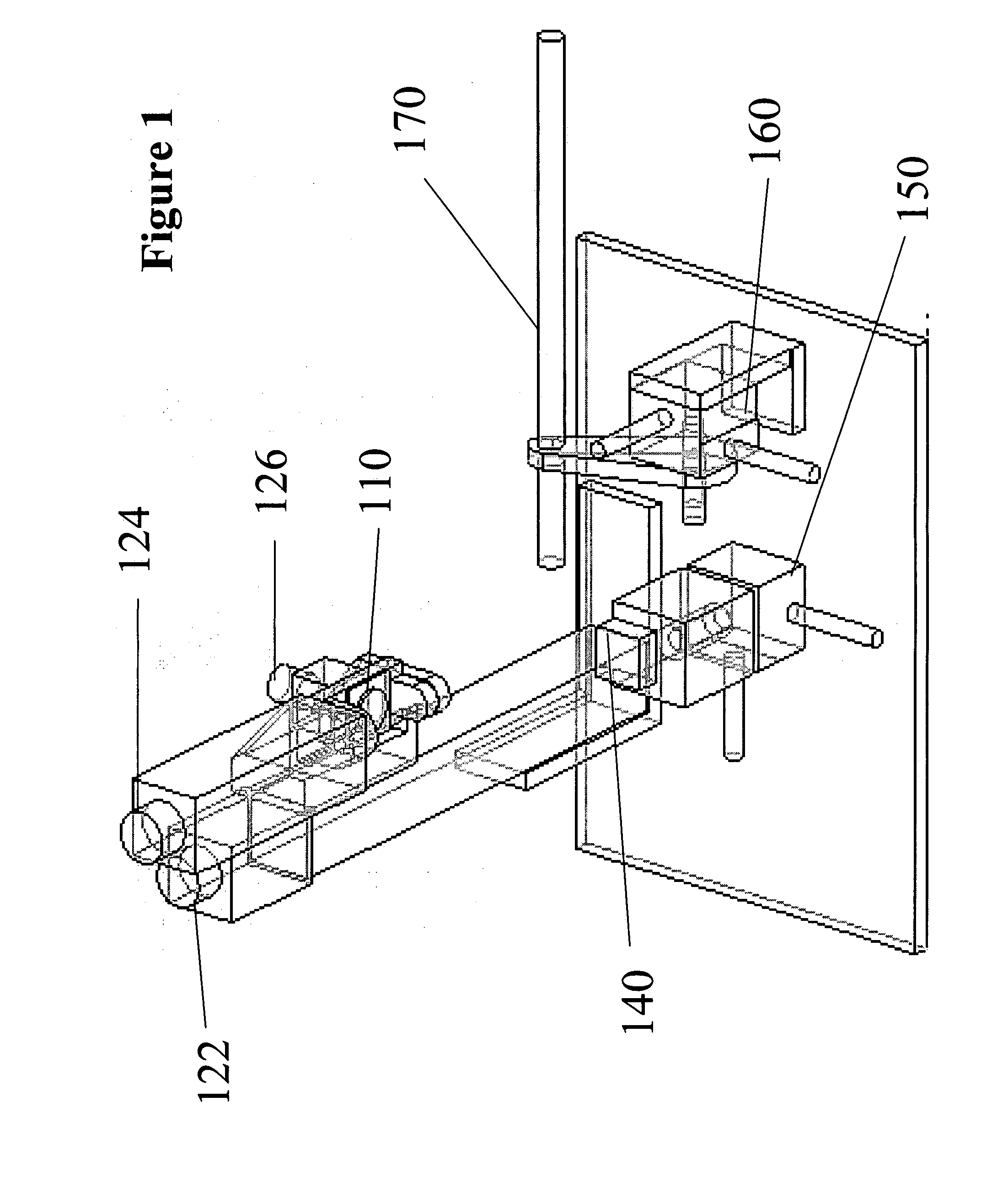
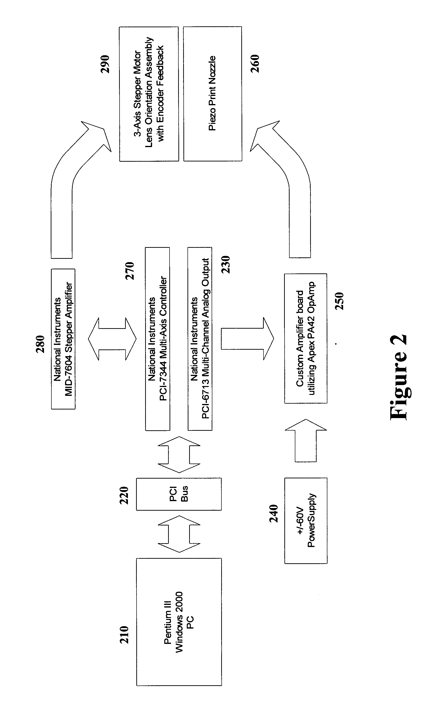
[0088] An apparatus, as depicted schematically in FIGS. 1 and 2, is designed to produce FreshLook™ (CIBA Vision) contact lenses by printing iris patterns onto male FreshLook polypropylene molds with recently developed ink jet inks for contact lenses, which are disclosed and claimed in a co-pending patent application, U.S. patent application Ser. No. ______, “Ink Formulations and Uses Thereof”, herein incorporated by reference in its entirety.

[0089] The apparatus comprises a Micro Fab print head (50 μm diameter). It has been discovered that heating the ink to ˜60° C. for 30 minutes followed by cooling may improve ink stability. Ink may show a sign of drying after a stagnation of about 20 minutes. The dried ink is easily removed by rinsing the tip of the head with water.

[0090] Piezoelectric firing is con...

example 2

[0096] This example illustrates the mass production of colored contact lens, Freshlook™, in an industrial setting according to a preferred embodiment of the invention.

[0097]FIG. 4 is a schematic flow diagram of a manufacturing process line for mass-production of FreshLook™ (CIBA Vision) contact lenses. Molds 410 for making contact lenses are transported into a hopper 420 which separates and places the male and female mold portions onto separate carrier pallets (male 432 and female 433) for rapid transport of multiple mold portions to the subsequent staging areas in the manufacturing line. Each of female mold portions is filled in a Filler 435 with enough lens material to make a contact lens and sent to the closing area 440. Each of male mold portions is sent to the ink jet printing station 434 (described below), where an inversion or iris pattern or both are jetted onto each of the male mold portions. Each of the male mold portions is then assembled tightly with one female mold por...

example 3

[0103] This example illustrates an inkjet printing system according to a preferred embodiment of the invention.

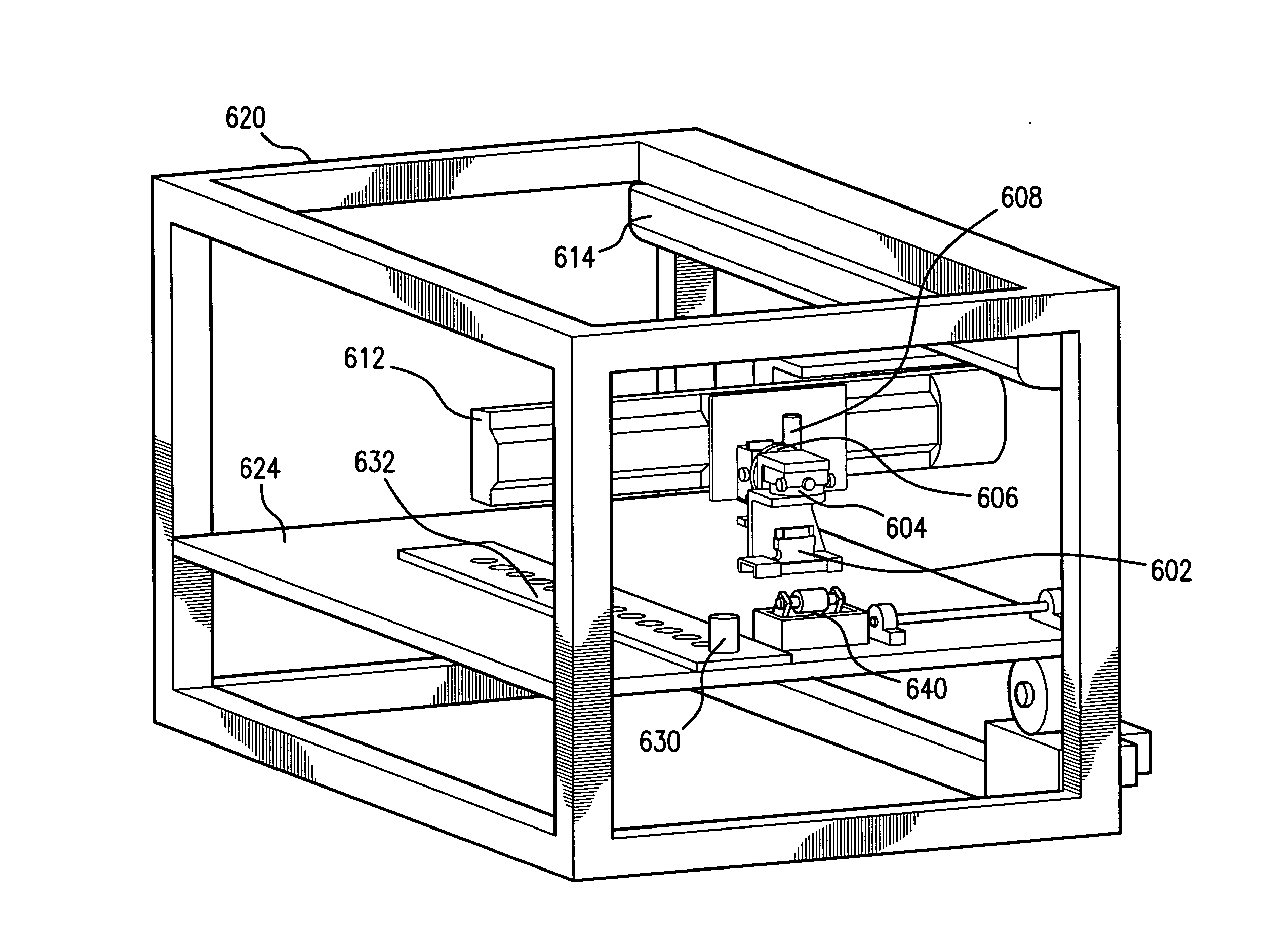
[0104]FIG. 6 schematically shows an inkjet printing system according to a preferred embodiment of the invention. The system comprises an inkjet printer head 602, which is connected to one or more ink reservoirs (not shown). Ink supply, pressure and flow are controlled by a computer system.

[0105] The inkjet printer head 602 (e.g., a XJ126 200 dpi inkjet head from Xaar) is mounted by mechanical fixtures known to a person skilled in the art onto a positioning system, which includes 2 rotary fixtures 604 and 606 (e.g., two 2″ rotary stages from Parker / Edmund Industrial), up-down linearly moving fixture 608 (e.g., a metric micrometer from Parker / Edmund Industrial), a first linear actuator 612 (e.g., a linear actuator, 300 mm stage from Intelligent Actuator) and a second linear actuator 614 (e.g., a linear actuator, 300 mm stage from Intelligent Actuator). The first and second ...


PUM

PropertyMeasurementUnit
molecular weightsaaaaaaaaaa
diameteraaaaaaaaaa
diameteraaaaaaaaaa

Abstract

The present invention provides a method for making colored contact lenses and an apparatus for implementing the method of the invention. The apparatus of the invention comprises a securing means for holding a contact lens or a portion of a mold for making the contact lens, a printer head, wherein the printer head comprises one or more nozzles each of which is capable of jetting droplets of color liquid independent of each other under control of a computer system; a positioning means for precisely positioning the printer head at each of a plurality of predetermined positions, one at a time, on a surface of the contact lens or the mold portion under control of the computer system. The method and apparatus of the invention are useful for producing colored contact lenses having high quality color images thereon.

Description

[0001] The present invention generally relates to systems and methods for making colored contact lenses. More specifically, the present invention relates to a digital printing system for printing a color image on curved surfaces of contact lenses or molds for making contact lenses. In addition, the present invention provides a manufacturing system and method for printing color images on curved surfaces of contact lenses or molds for making contact lenses. BACKGROUND [0002] For cosmetic purposes, contact lenses having one or more colorants dispersed in the lens or printed on the lens are in high demand. These colored contact lenses enhance the natural beauty of the eye, or provide unique patterns on the iris of the wearer, or provide non cosmetic patterns or marks, such as rotation marks, inversion marks, product / brand codes, lot numbers, “DEMO” lenses, and the like, which are of benefits to wearers, eye-care practitioners and manufacturers. [0003] Presently, methods of printing inks...

Claims


Application Information

Patent Timeline
Patent Type & Authority Applications(United States)
IPC IPC(8): B41J3/407B41J29/38B41J2/01G02C7/04
CPCB41J3/407B41J3/4073B41J2/16585B41M3/003G02B1/043B41J3/543B41M5/0088
Inventor TUCKER, ROBERT CAREYHYINK, DAVID
Owner ALCON INC
Why Eureka
Try Eureka