
Method for manufacturing liquid crystal display devices and devices manufactured thereby

a liquid crystal display and manufacturing method technology, applied in non-linear optics, instruments, optics, etc., can solve the problems of reducing affecting not being very stable under high intensity illumination. , to achieve the effect of facilitating an increase in the reliability of the device, reducing the instances of device failure, and increasing the functional life of the lcd devi

Active Publication Date: 2007-11-29
OMNIVISION TECH INC
View PDF16 Cites 11 Cited by
  • Summary
  • Abstract
  • Description
  • Claims
  • Application Information

AI Technical Summary

Benefits of technology

The barrier layer effectively prevents impurity absorption, maintains alignment layer functionality, and reduces gasket width, enhancing the reliability and yield of LCD devices by minimizing contamination and material costs.

Problems solved by technology

One common limitation of polyimide alignment layers is that they are not very stable under high intensity illumination.
A problem has arisen, however, with devices incorporating evaporated thin film alignment layers.
This change affects both the contrast and color of the projected image and so is deemed unacceptable for consumer applications.
The gradual failure of LCD devices appearing over time can be particularly costly and bothersome to manufacturers because the devices will most likely have been incorporated into other products by the time the defects become apparent.
Then, failure of the device can result in diminished optical performance of the product, costly warranty repairs, and / or costly product recalls.
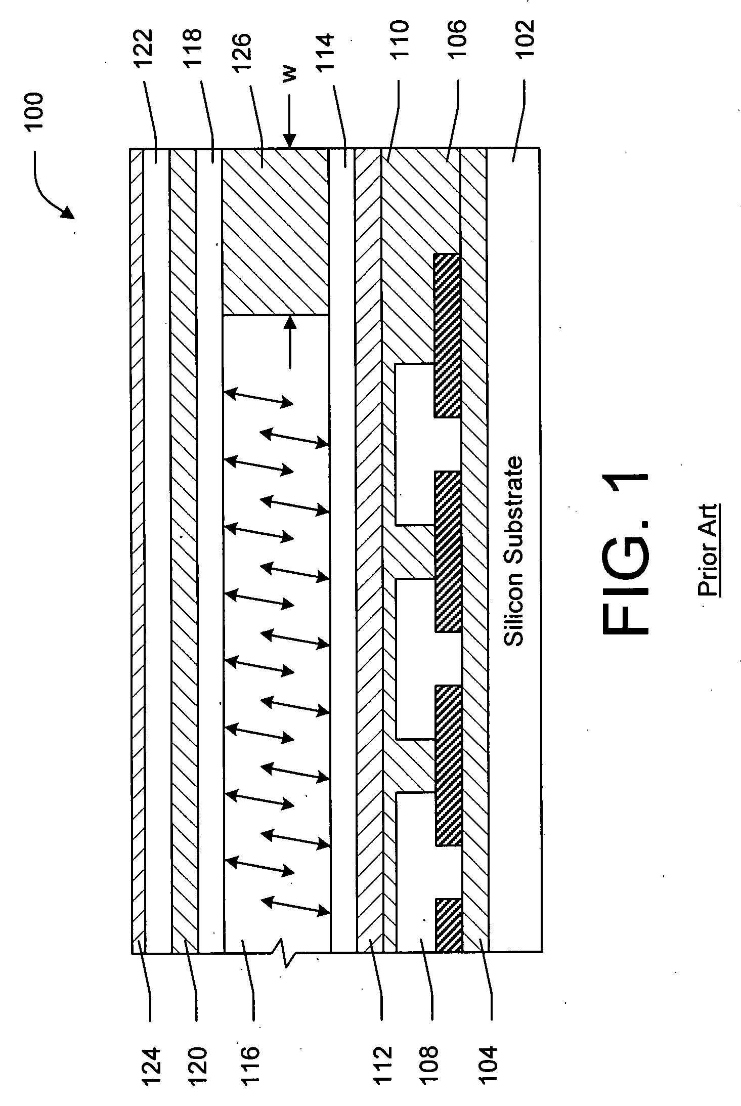
Despite the sealing properties of gasket 126, LCD device 100 will still experience performance degradations over time.
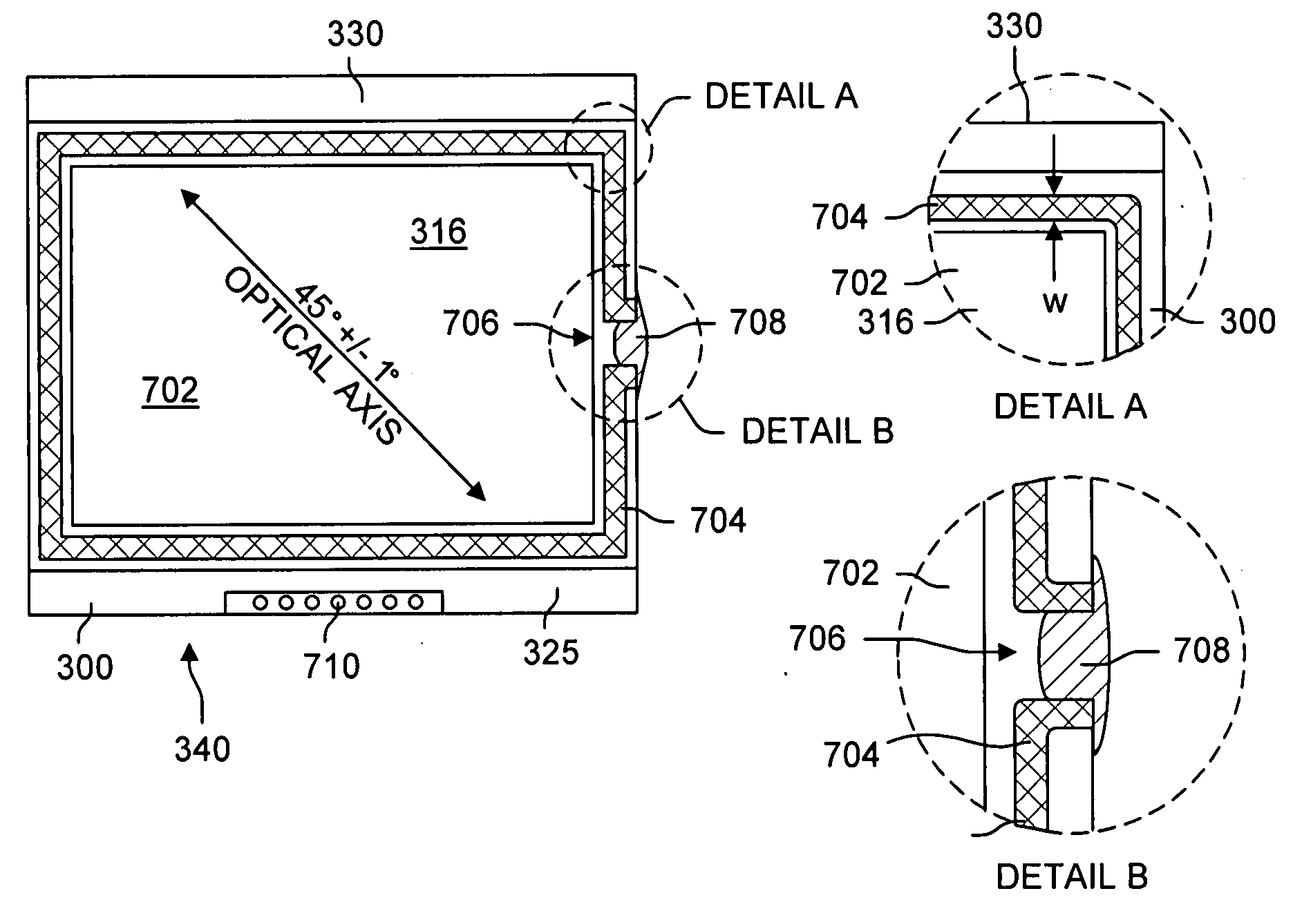
Another problem associated with gasket 126 is that in prior art devices gasket 126 must be relatively wide and takes up a large amount of area on LCD device 100.
This in turn significantly reduces the number of display devices that can be produced from a single silicon wafer.
The inventors have found that the catastrophic failure of many LCD display devices arising over time is much more prevalent when environmental stress factors such as heat and humidity are present.
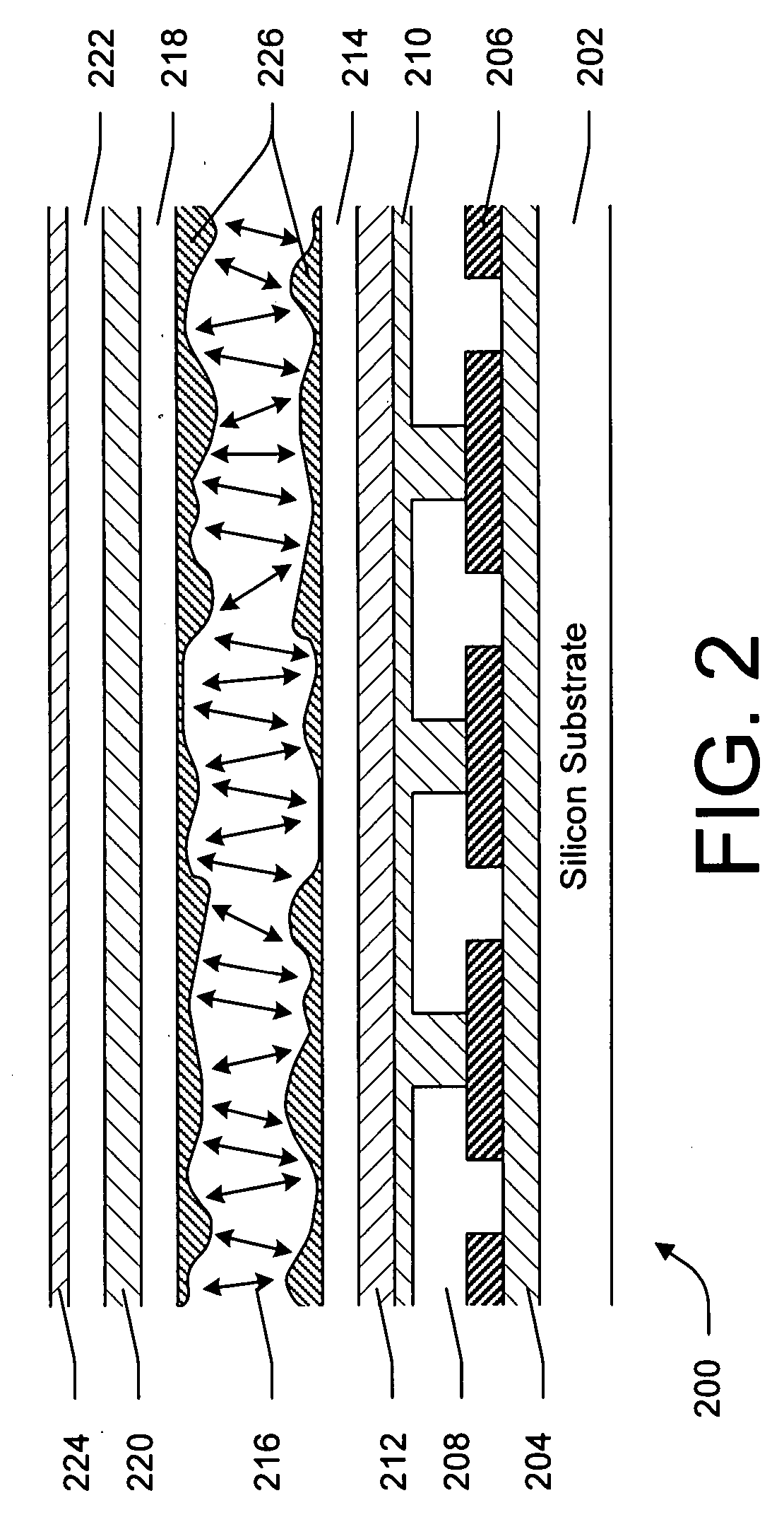
The absorption and / or adsorption of impurities interferes with the function of the alignment layers and causes perceptible image defects.
In some cases, non-uniform layers of impurity deposits form on the liquid crystal alignment layers.
The non-uniform impurity deposit layers consequently result in a skewing of the alignment of the liquid crystals within the liquid crystal layer, resulting in perceptible image defects and / or catastrophic failure of the device.

Method used


Image

  • Method for manufacturing liquid crystal display devices and devices manufactured thereby
  • Method for manufacturing liquid crystal display devices and devices manufactured thereby
  • Method for manufacturing liquid crystal display devices and devices manufactured thereby

Examples


Embodiment Construction

[0043] The present invention overcomes the problems associated with the prior art, by providing a means for protecting the liquid crystal alignment layers of a liquid crystal display (LCD) device against contamination that interferes with the communication of the anisotropic properties of the liquid crystal alignment layers to the liquid crystal layer of the device. In the following description, numerous specific details are set forth (e.g., particular methods of forming a barrier layer, particular display type, particular reagents used to form barrier layers, etc.) in order to provide a thorough understanding of the invention. Those skilled in the art will recognize, however, that the invention may be practiced apart from these specific details. In other instances, details of well known LCD display manufacturing practices (e.g., substrate manufacturing, liquid crystal types, liquid crystal cell assembly, electrical connections, etc.) and components have been omitted, so as not to u...


PUM

PropertyMeasurementUnit
widthaaaaaaaaaa
widthaaaaaaaaaa
widthaaaaaaaaaa

Abstract

A liquid crystal display device includes a substrate, a liquid crystal layer, a liquid crystal alignment layer between the substrate and the liquid crystal layer, a barrier layer between the liquid crystal alignment layer and the liquid crystal layer, and a gasket formed around the perimeter of the liquid crystal layer and abutting the barrier layer. The gasket has a width less than or equal to 400 micrometers. A second substrate also includes a liquid crystal alignment layer and a barrier layer formed over the liquid crystal alignment layer. The gasket also abuts the barrier layer of the second substrate. In a particular embodiment, the substrate is a reflective display backplane, and the second substrate is a transparent substrate having a transparent electrode layer. The gasket of the present invention is much narrower than gaskets of the prior art, which enables LCD devices to be made smaller and cheaper because more LCD devices can be produced per wafer.

Description

[0001] This application is a continuation-in-part of co-pending U.S. patent application Ser. No. 11 / 125,838, filed May 10, 2005 by the same inventors, which is incorporated herein by reference in its entirety.BACKGROUND OF THE INVENTION [0002] 1. Field of the Invention [0003] This invention relates generally to liquid crystal display (LCD) devices, and more particularly to a method of manufacturing LCD devices. Even more particularly the present invention relates to manufacturing processes and the LCD display devices manufactured thereby that decrease the incidence of defects arising over time, including the catastrophic failure of liquid crystal on silicon (LCoS) light valves. Furthermore, the present invention also relates to LCD display devices and manufacturing processes that increase the yield of LCD display devices from a single wafer. [0004] 2. Description of the Background Art[0005] Reflective and transmissive liquid crystal display (LCD) devices are used in video projectors...

Claims


Application Information

Patent Timeline
Patent Type & Authority Applications(United States)
IPC IPC(8): G02F1/1335G02F1/1337
CPCG02F1/133553G02F2201/50G02F2001/133337G02F1/136277G02F1/133337
Inventor BONE, MATTHEW F.SKALFE, JUSTIN JOHN
Owner OMNIVISION TECH INC
Learn More