
Fluid Dynamic Bearing Device

a dynamic bearing and bearing technology, applied in sliding contact bearings, other domestic objects, instruments, etc., can solve the problems of increasing the frequency of contact between the reinforcement fiber and the mating resin member, the fear of reinforcement fiber blended in one resin member flawing, etc., to achieve high impact resistance, high fixation strength, and reduce weight and production cost

Inactive Publication Date: 2007-11-29
NTN CORP
View PDF9 Cites 14 Cited by
  • Summary
  • Abstract
  • Description
  • Claims
  • Application Information

AI Technical Summary

Benefits of technology

[0007] It is an object of the present invention to provide a fluid dynamic bearing device which exhibits high durability and which can be manufactured at low cost.

Problems solved by technology

When such the sliding contact occurs between members formed of resins, there is a fear of reinforcement fibers blended in one resin member flawing or wearing a mating member.
An examination conducted by the present inventors has shown that when a diameter of the reinforcement fibers blended in the resin is too large, a rigidity of the reinforcement fibers increases, with the result that flaws and wear are caused in the mating resin member during sliding, and that too large a blending amount of reinforcement fibers leads to an increase in frequency of contact between the reinforcement fibers and the mating resin member, resulting in a similar problem.
It has become clear that, in the former case, this problem occurs when the fiber diameter exceeds 12 μm, and that, in the latter case, this problem occurs when the blending amount exceeds 20 vol %.

Method used


Image

  • Fluid Dynamic Bearing Device
  • Fluid Dynamic Bearing Device
  • Fluid Dynamic Bearing Device

Examples


Embodiment Construction

[0049] In the following, embodiments of the present invention will be described with reference to FIGS. 1 through 13.

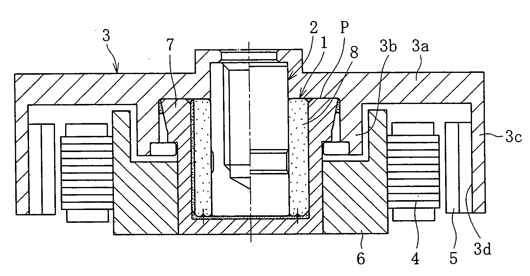
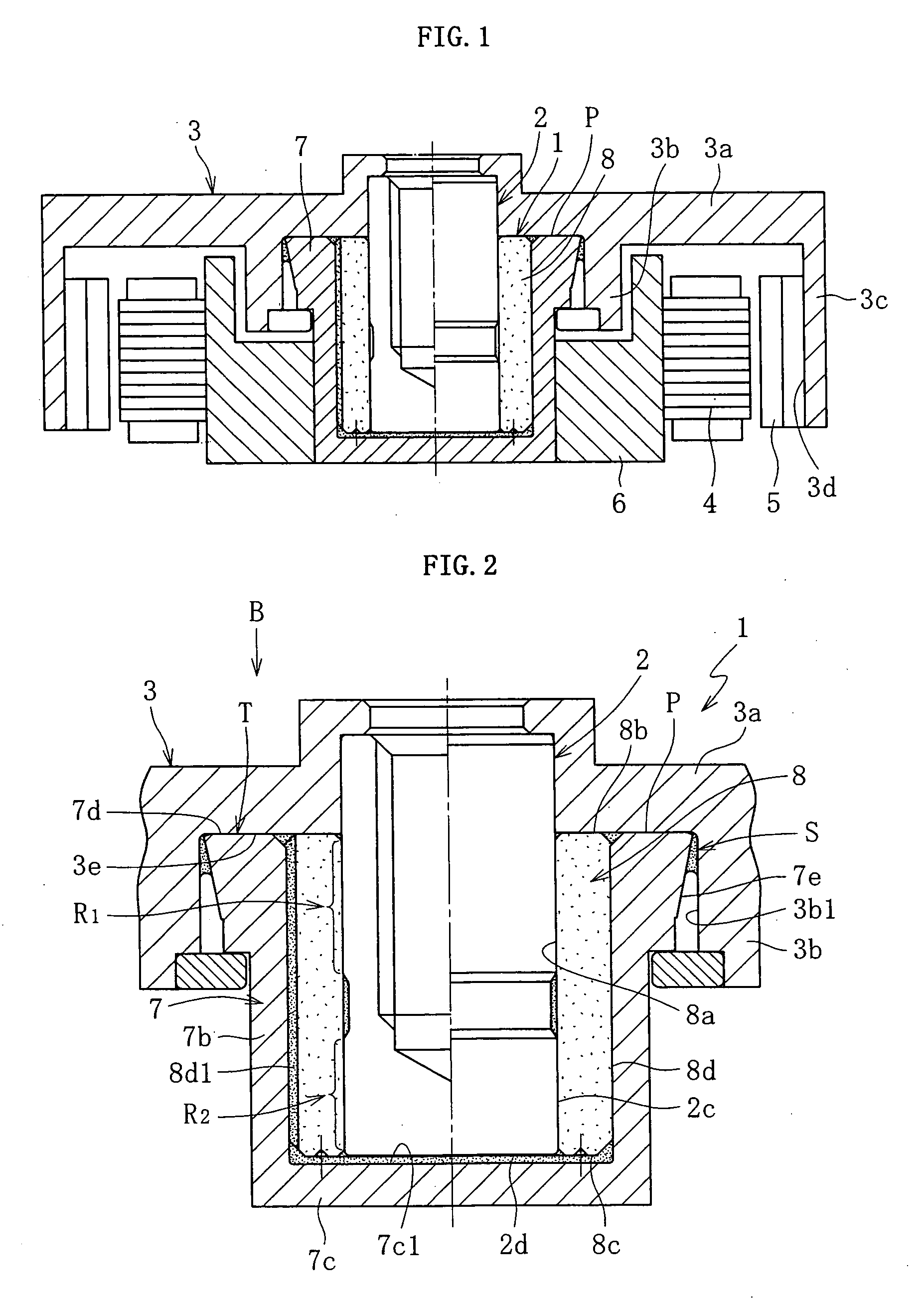
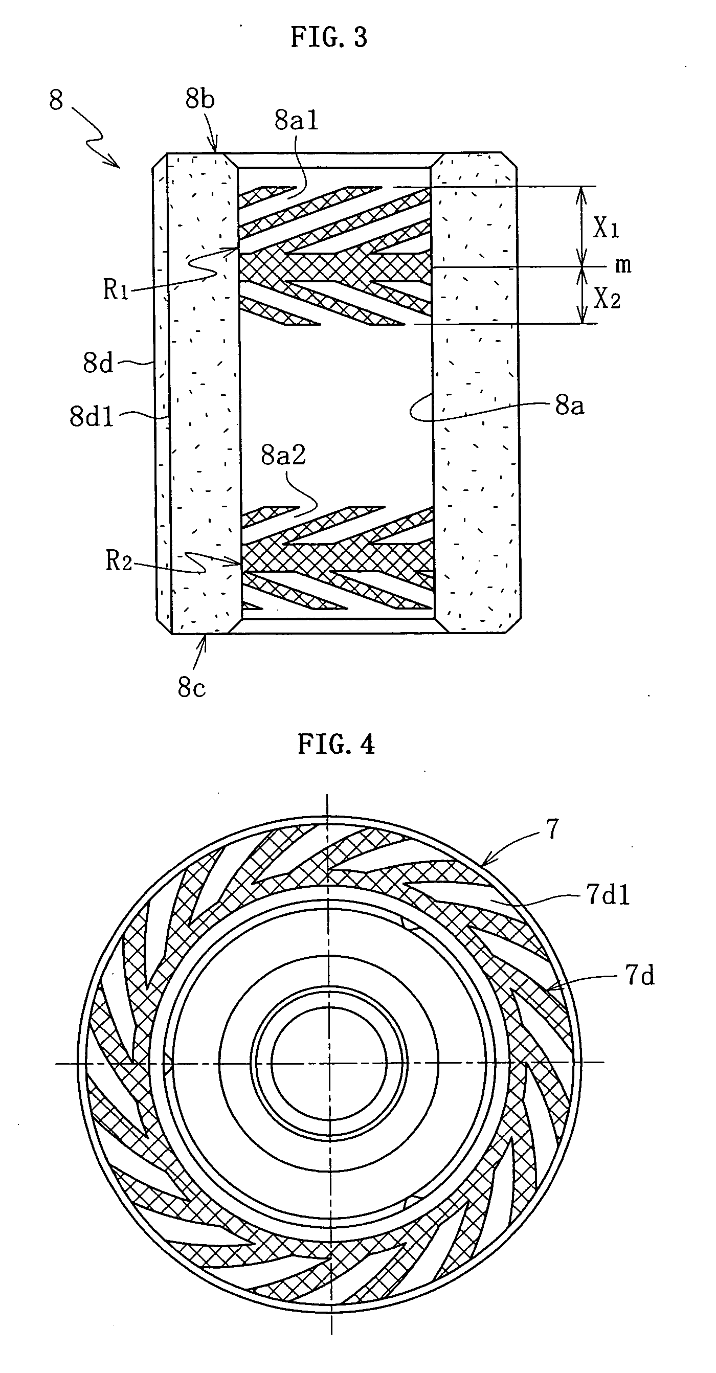
[0050]FIG. 1 shows a construction example of an information apparatus spindle motor in which a fluid dynamic bearing device 1 according to an embodiment of the present invention is incorporated. The spindle motor is used in a disk drive device, such as an HDD, and is equipped with a fluid dynamic bearing device 1 rotatably supporting a shaft member 2 in a non-contact fashion, a disk hub 3 attached to the shaft member 2, and a stator coil 4 and a rotor magnet 5 opposed to each other through the intermediation of, for example, a radial gap. The disk hub 3, for retaining one or a plurality of disks, such as magnetic disks, has the rotor magnet 5 attached to the inner periphery thereof. The stator coil 4 is mounted to the outer periphery of a bracket 6 fixed to the outer periphery of a housing 7 of the fluid dynamic bearing device 1. When the stator coil 4 is energized, ...


PUM

PropertyMeasurementUnit
diameteraaaaaaaaaa
vol %aaaaaaaaaa
vol %aaaaaaaaaa

Abstract

The present invention provides a fluid dynamic bearing device having high durability and capable of being produced at low cost. In the fluid dynamic bearing device, a housing (7) and a disc hub (3) are resin molded parts, and a thrust bearing gap is formed between an upper end surface (7d) of the housing (7) and a lower end surface (3e) of the disc hub (3). In this case, the surfaces (7d, 3e) function as sliding portions (P) temporarily in sliding contact with each other during operation of the bearing. A diameter of PAN-based carbon fibers blended as reinforcement fibers in the resin housing (7) is 12 μm or less, and the blending amount is within a range of 5 to 20 vol %, thereby making it possible to prevent occurrence of flaws and wear in the sliding portions (P).

Description

BACKGROUND OF THE INVENTION [0001] 1. Field of the Invention [0002] The present invention relates to a fluid dynamic bearing device. This fluid dynamic bearing is suitable as a bearing device for use in a spindle motor for an information apparatus, for example, a magnetic disk apparatus, such as an HDD or an FDD, an optical disk apparatus, such as a CD-ROM, a CD-R / RW, or a DVD-ROM / RAM, or a magneto-optical disk apparatus, such as an MD or an MO, a polygon scanner motor for a laser beam printer (LBP), a color wheel motor for a projector, or a small motor for an electric apparatus, such as an axial flow fan. [0003] 2. Description of the Related Art [0004] Apart from high rotational accuracy, an improvement in speed, a reduction in cost, a reduction in noise, etc. are required of the various motors mentioned above. One of the factors determining such requisite performances is a bearing supporting a spindle of the motor. Recently, as a bearing of this type, use of a fluid dynamic bearin...

Claims


Application Information

Patent Timeline
Patent Type & Authority Applications(United States)
IPC IPC(8): F16C32/06B29D22/00H02K5/00B32B25/00F16C17/10F16C33/10F16C33/20G11B19/20H02K7/08
CPCF16C17/107F16C33/107Y10T428/1352G11B19/2018F16C2370/12F16C33/201
Inventor SHIBAHARA, KATSUOITO, KENJIKOMORI, ISAONAKAJIMA, RYOUICHIKURIMURA, TETSUYA
Owner NTN CORP
Learn More