Multiple-core photonic-bandgap fiber with coupling between the cores

Active Publication Date: 2007-11-29
THE BOARD OF TRUSTEES OF THE LELAND STANFORD JUNIOR UNIV
View PDF14 Cites 14 Cited by
  • Summary
  • Abstract
  • Description
  • Claims
  • Application Information

AI Technical Summary

Problems solved by technology

In addition, the propagation loss in hollow-core PBFs is not limited by the core material, and it is expected that the propagation loss can be exceedingly low.
However, this approach suffers from various shortcomings.
Butt-coupled junctions often do not provide sufficient mechanical stability, and splices of dissimilar fibers can introduce significant amou

Method used


Image

  • Multiple-core photonic-bandgap fiber with coupling between the cores
  • Multiple-core photonic-bandgap fiber with coupling between the cores
  • Multiple-core photonic-bandgap fiber with coupling between the cores

Examples


Example

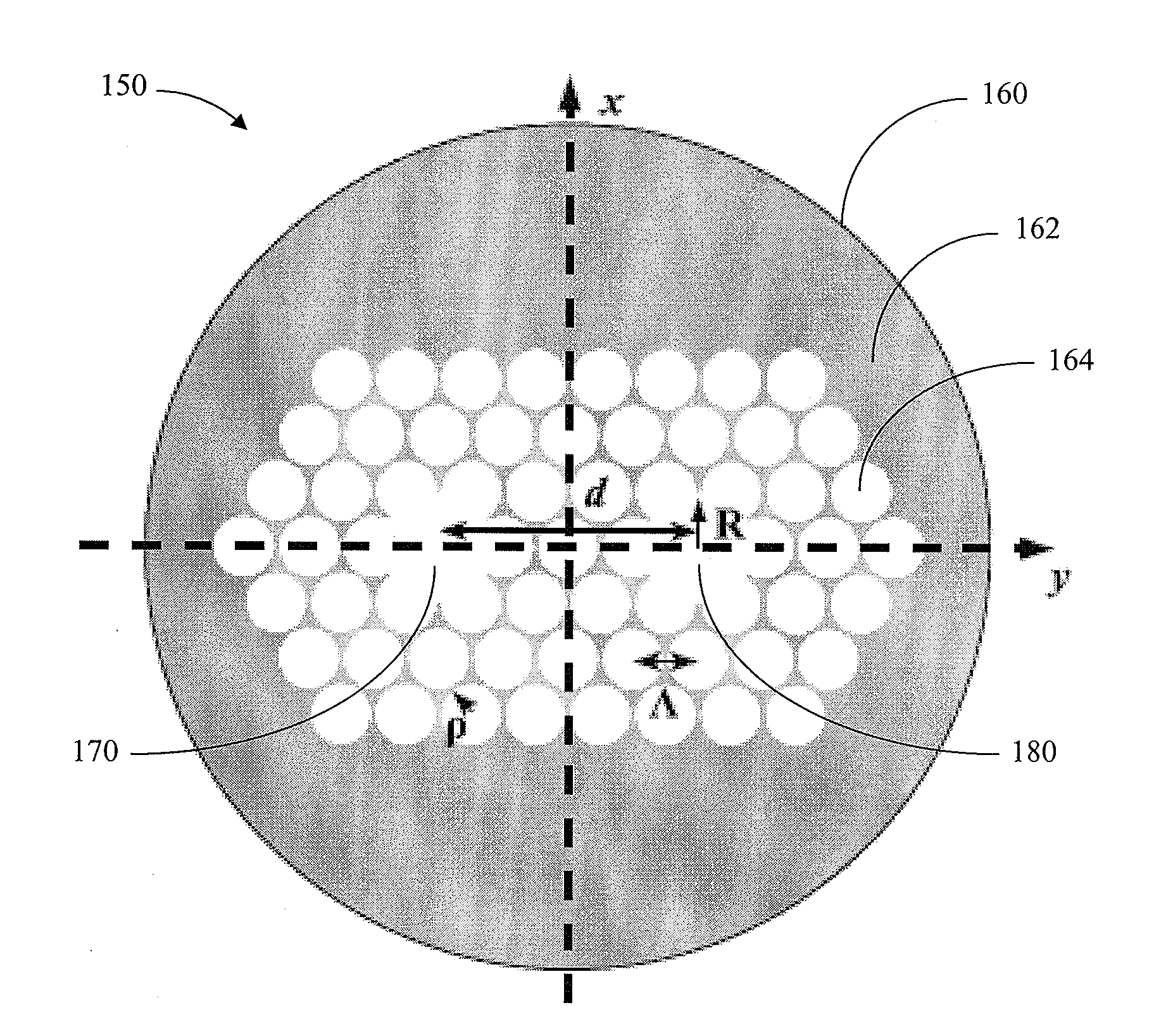
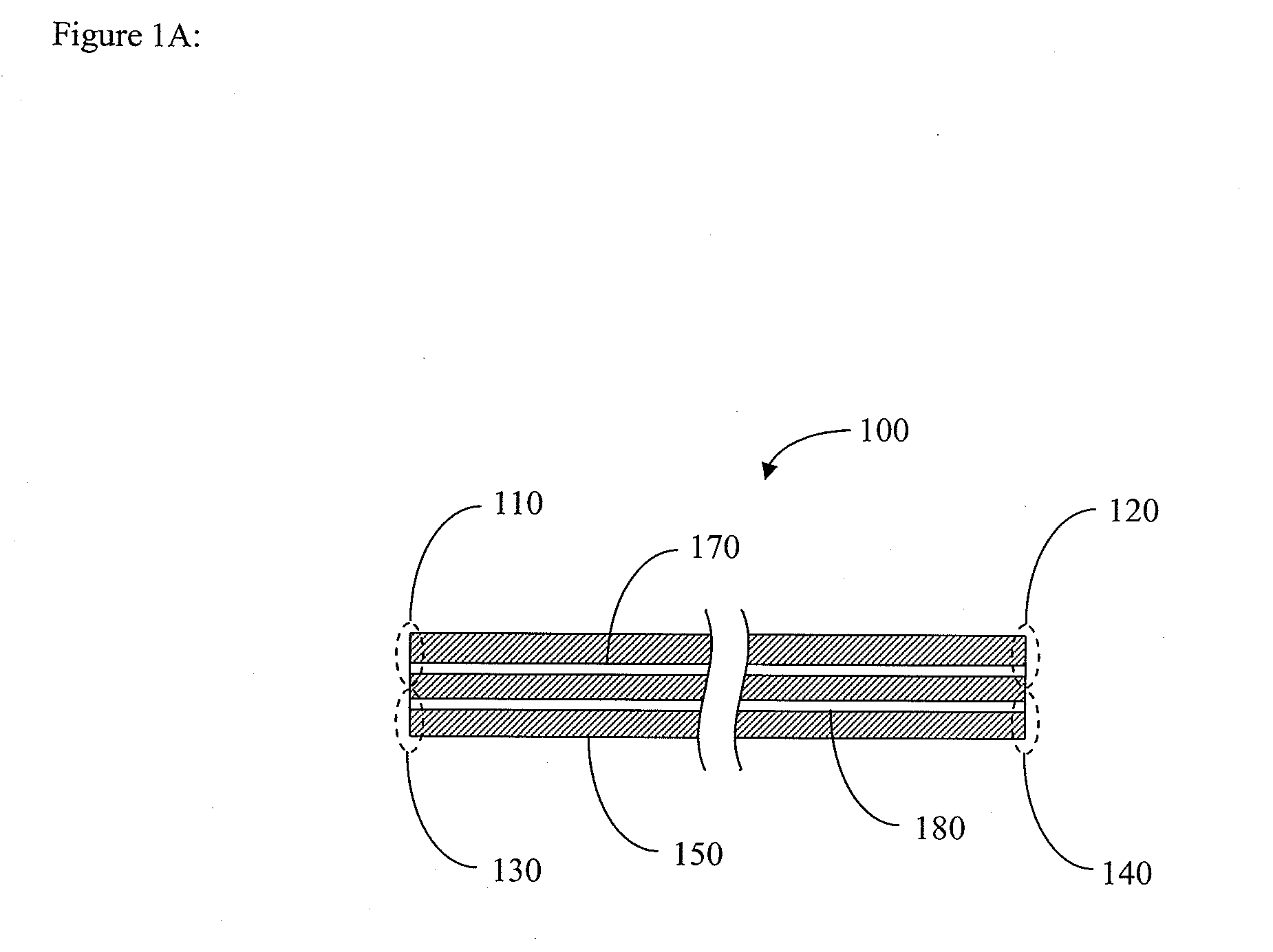
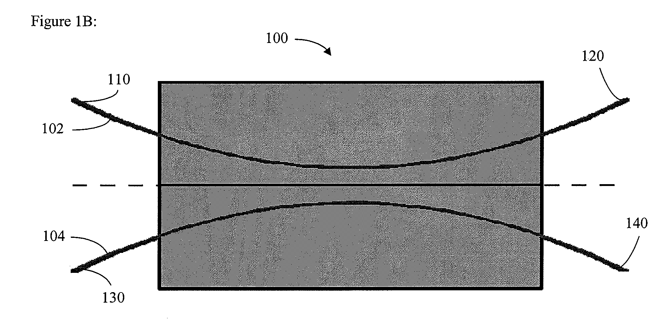
[0031]FIG. 1A schematically illustrates an example optical coupler 100 in accordance with certain embodiments described herein. The optical coupler 100 comprises a first optical port 110, a second optical port 120, a third optical port 130, and a fourth optical port 140. The optical coupler 100 further comprises a two-core photonic-bandgap fiber (PBF) 150 comprising a cladding 160, a first core 170, and a second core 180. The first core 170 is optically coupled to the first optical port 110 and to the second optical port 120. The second core 180 is optically coupled to the third optical port 130 and to the fourth optical port 140. In certain embodiments, the first optical port 110 comprises a first portion of the first core 170, and the second optical port 120 comprises a second portion of the first core 170. In certain embodiments, the third optical port 130 comprises a first portion of the second core 180, and the fourth optical port 140 comprises a second portion of the second co...


PUM


Abstract

An optical coupler includes a first optical port, a second optical port, a third optical port, and a fourth optical port. The optical coupler further includes a photonic-bandgap fiber having a cladding, a first core, and a second core. The cladding includes a material with a first refractive index and regions within the cladding. The regions have a second refractive index lower than the first refractive index. The first core is substantially surrounded by the cladding. The first core is optically coupled to the first optical port and to the second optical port. The second core is substantially surrounded by the cladding. The second core is optically coupled to the third optical port and to the fourth optical port. At least a portion of the first core is generally parallel to and spaced from at least a portion of the second core such that the first core is optically coupled to the second core. The first core, the second core, or both the first core and the second core is hollow.

Description

CLAIM OF PRIORITY [0001] This application claims the benefit of U.S. Provisional Patent Application No. 60 / 778,229, filed Mar. 2, 2006, which is incorporated in its entirety by reference herein.BACKGROUND OF THE INVENTION [0002] 1. Field of the Invention [0003] This application relates generally to optical devices utilizing photonic-bandgap fibers. [0004] 2. Description of the Related Art [0005] Photonic-crystal fibers have been the subject of much interest and developments in recent years. (See, e.g., J. Broeng et al., “Photonic crystal fibers: A new class of optical waveguides,” Optical Fiber Technology, Vol. 5, pages 305-330 (1999); J. C. Knight et al., “Photonic crystals as optical fibers—physics and applications,” Optical Materials, Vol. 11, pages 143-151 (1999); R. S. Windeler et al., “Silica-air microstructured fibers: Properties and applications,” Optical Fiber Communications conference, San Diego, Calif. (1999).) Because of their unique properties, including low optical non...

Claims


Application Information

Patent Timeline
IPC IPC(8): G02B6/036
CPCG02B6/02042G02B6/02328G02B6/2821G02B6/02347G02B6/02338
Inventor DANGUI, VINAYAKDIGONNET, MICHEL J. F.KINO, GORDON S.
Owner THE BOARD OF TRUSTEES OF THE LELAND STANFORD JUNIOR UNIV
Why Eureka
Try Eureka