Optical fiber amplifier and dispersion compensating fiber module for optical fiber amplifier

a technology of optical fiber amplifier and optical fiber amplifier, which is applied in the direction of multiplex communication, wavelength-division multiplex system, active medium material, etc., can solve the problems of accumulating dispersion amount, degrading conversion efficiency, and unstable operation of pump sour

Inactive Publication Date: 2002-01-29
FUJITSU LTD
View PDF15 Cites 86 Cited by
  • Summary
  • Abstract
  • Description
  • Claims
  • Application Information

AI Technical Summary

Benefits of technology

It is an object of the present invention to provide an optical fiber amplifier wherein stable operation of a pump source (pump light source) is assured and residual pump power which is produced when the average pump ratio is raised is utilized efficiently to improve the conversion efficiency.
Also in the modified optical fiber amplifier, pump light is introduced into one end of the erbium-doped-fiber 11-1 from the optical demultiplexer-multiplexer 13-1 by way of the optical circulator 15. Then, residual pump light originating from the pump light introduced into the erbium-doped-fiber 11-1 and arriving at the other end of the erbium-doped-fiber 11-1 is demultiplexed by the optical demultiplexer-multiplexer 13-2 and then reflected by the reflecting mirror 14 so that it is introduced back into the erbium-doped-fiber 11-1. The reflected residual light introduced into the erbium-doped-fiber 11-1 is introduced, after passing the erbium-doped-fiber 11-1, into a different optical path by the optical circulator 15 so that it is introduced into and multiplexed by the optical demultiplexer-multiplexer 13-3 with signal light, and the thus multiplexed light is introduced into and amplified by the erbium-doped-fiber 11-2. Consequently, similar advantages or effects to those of the first embodiment described hereinabove with reference to FIG. 16 can be achieved. In addition, since the pump source 12-1 is provided commonly for the two erbium-doped-fibers 11-1 and 11-2, the optical fiber amplifier is simplified in construction and reduced in cost.

Problems solved by technology

However, if the doped fiber is formed short in this manner, then much residual pump power will leak out from the other end of the doped fiber, resulting in degradation of the conversion efficiency.
In particular, although it is apparent from the conservative law of energy that the pump power increases as the number of wavelengths increases, a wavelength multiplexing optical amplifier cannot be used in a condition in which it exhibits a high efficiency of conversion from pump power to signal power.
This pump light may possibly give rise to unstable operation of the pump source such as interference.
However, in an optical-amplifier-repeated transmission system, since a transmitted optical signal is repeated by a kind of analog amplification, the dispersion amount is accumulated.
Generally, however, the mode field diameter of a dispersion compensating fiber (DCF) is set small in order to compensate for a dispersion, and consequently, nonlinear effects are liable to occur and, as the dispersion amount to be compensated for increases, also the loss increases.
Accordingly, the possible method has a problem in that designing of a level diagram is difficult.
Accordingly, there is a subject to be solved in that it is difficult to realize a flat and wide amplification bandwidth.
If such unnecessary oscillations are produced, the rare earth doped fiber optical amplifier operates but unstably.
For example, in an erbium-doped-fiber optical amplifier, spontaneous emission light (ASE) of 1.53 to 1.57 .mu.m in wavelength is generated when optical amplification is performed, and since the ASE is repetitively reflected from reflection points in the erbium-doped-fiber optical amplifier, unnecessary oscillations are liable to be produced.
Particularly with an erbium-doped-fiber optical amplifier adjusted for multiple wavelength collection amplification (that is, an erbium-doped-fiber optical amplifier having a high pump rate), since it has a high gain in the proximity of 1.53 .mu.m, unnecessary oscillations are liable to be produced at this wavelength.
When such unnecessary oscillations are produced, the erbium-doped-fiber optical amplifier operates but unstably.

Method used


Image

  • Optical fiber amplifier and dispersion compensating fiber module for optical fiber amplifier
  • Optical fiber amplifier and dispersion compensating fiber module for optical fiber amplifier
  • Optical fiber amplifier and dispersion compensating fiber module for optical fiber amplifier

Examples


first embodiment

B1. First Embodiment

Referring now to FIG. 16, there is shown in block diagram an optical fiber amplifier according to a first preferred embodiment of the present invention. The optical fiber amplifier shown includes a pair of erbium-doped-fibers (EDF) 11-1 and 11-2 each as a rare earth doped fiber, a pair of pump sources 12-1 and 12-2, four optical demultiplexer-multiplexers (WDM; optical wave separator-combiners) 13-1 to 13-4 serving as first to fourth optical couplers, respectively, a reflecting mirror (reflection element) 14, an optical circulator 15, three isolators (ISO) 16-1 to 16-3, and an optical filter 17.

In particular, in the optical fiber amplifier, the isolator 16-1, optical demultiplexer-multiplexer 13-1, erbium-doped-fiber 11-1, optical demultiplexer-multiplexer 13-2, optical filter 17, isolator 16-2, optical demultiplexer-multiplexer 13-3, erbium-doped-fiber 11-2, optical demultiplexer-multiplexer 13-4 and isolator 16-3 are arranged in this order from the input side.

T...

second embodiment

B2. Second Embodiment

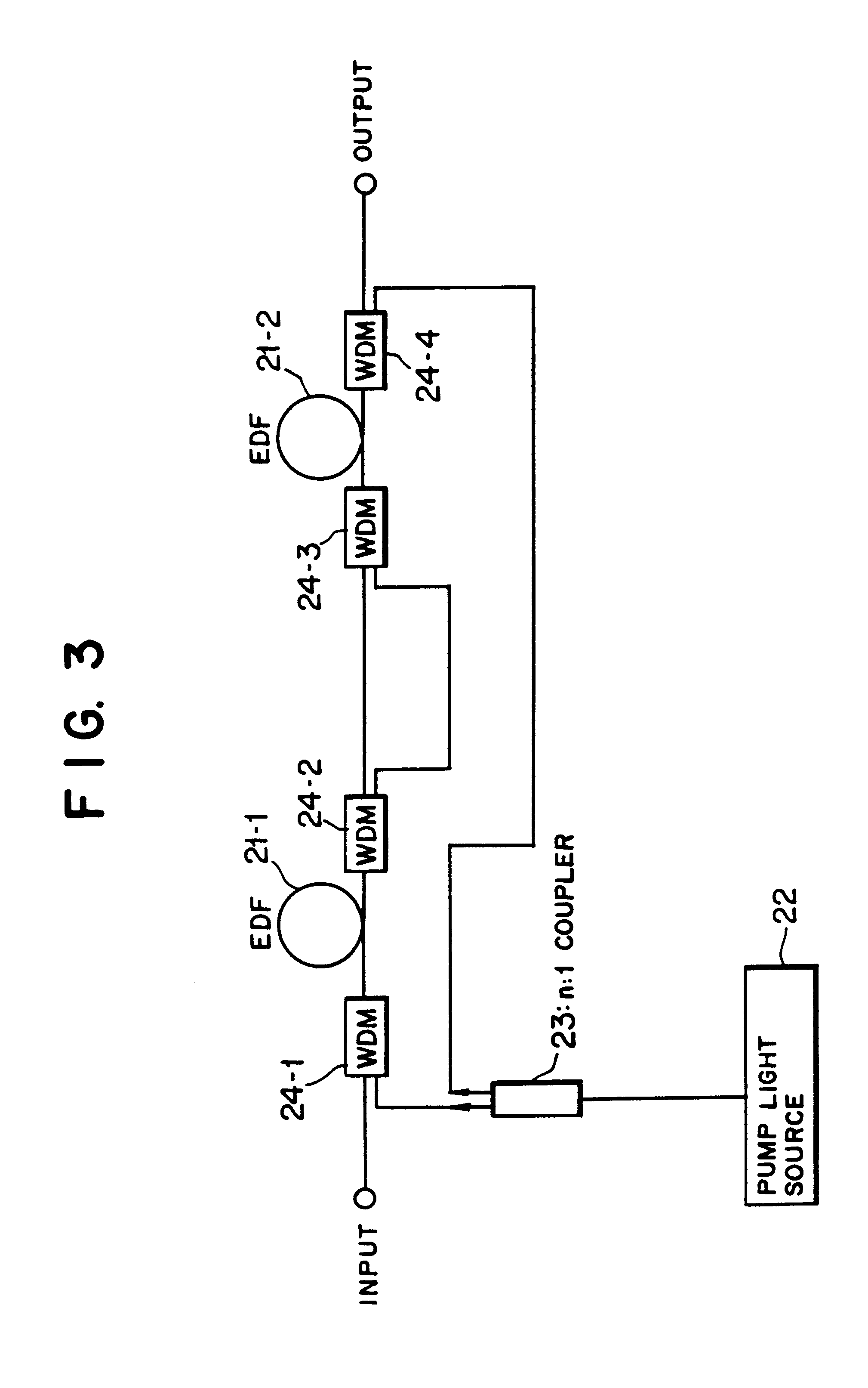
FIG. 23 is a block diagram showing a second preferred embodiment of the present invention. Referring to FIG. 23, the optical fiber amplifier shown includes an isolator 25-1, an optical demultiplexer-multiplexer (first coupler) 24-1, an erbium-doped-fiber (rare earth doped fiber) 21-1, another optical demultiplexer-multiplexer (second coupler) 24-2, an optical filter 26, another isolator 25-3, a further optical demultiplexer-multiplexer (third coupler) 24-3, another erbium-doped-fiber (rare earth doped fiber) 21-2, a still further optical demultiplexer-multiplexer (fourth coupler) 24-4 and a further isolator 25-4 disposed in this order from the input side.

An optical signal line including the optical filter 26 and the isolator 25-3 and a pump light line are provided in parallel between the optical demultiplexer-multiplexers 24-2 and 24-3.

A pump source 22 is connected to the optical demultiplexer-multiplexer 24-1 by way of an optical branching element 23 and a stil...

third embodiment

B3. Third Embodiment

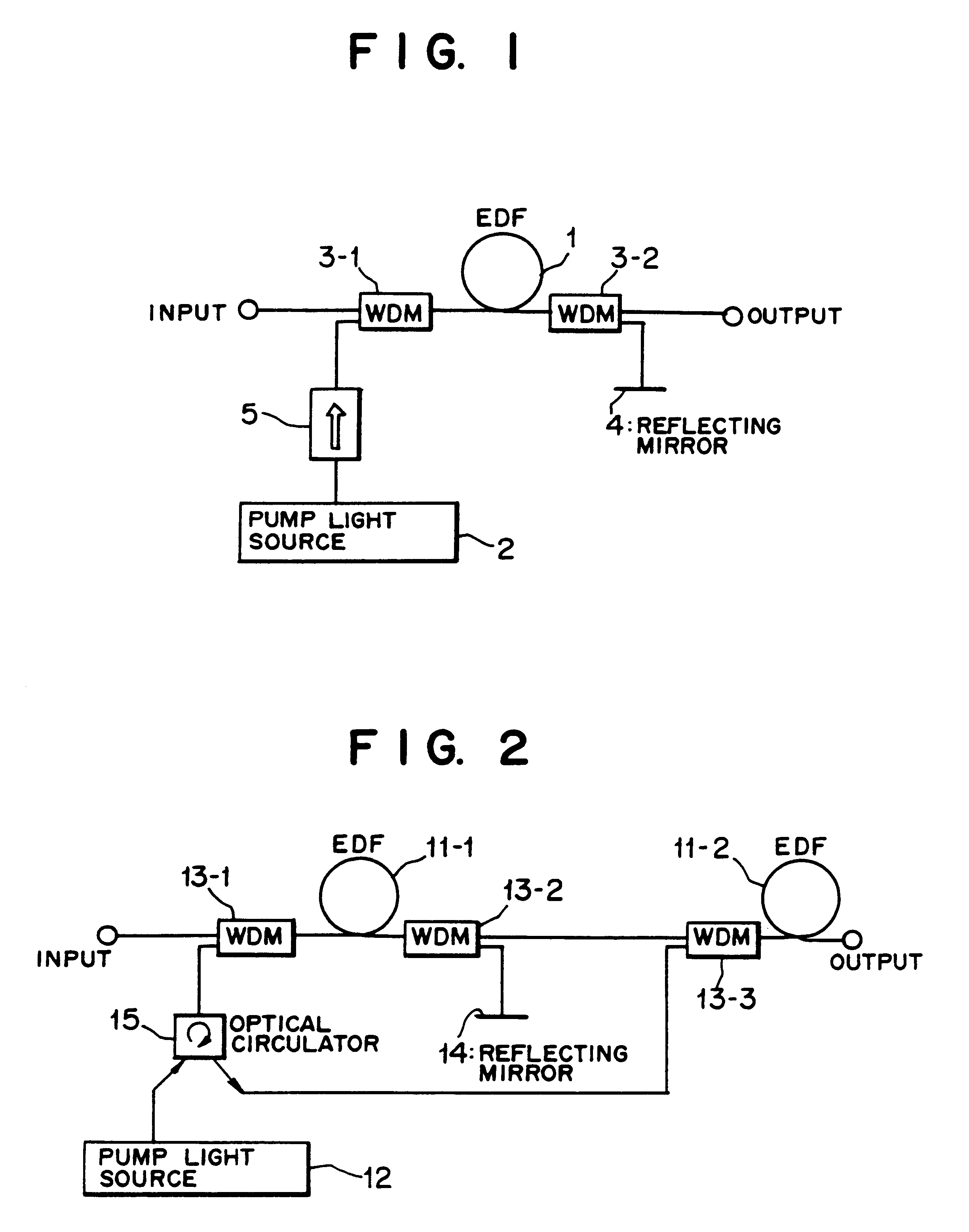
FIG. 25 is a block diagram showing a third preferred embodiment of the present invention. Referring to FIG. 25, the optical fiber amplifier shown includes an isolator 5-1, an optical demultiplexer-multiplexer 3-1, an erbium-doped-fiber (rare earth doped fiber) 1, another optical demultiplexer-multiplexer 3-2, and another isolator 5-3 disposed in this order from the input side. A pump source 2 is connected to the optical demultiplexer-multiplexer 3-1 by way of a further isolator 5-2. A reflecting mirror (reflection element) 4 is connected to the optical demultiplexer-multiplexer 3-2.

In particular, the optical fiber amplifier shown in FIG. 25 includes a first element for introducing pump light into an input end of the erbium-doped-fiber 1 by means of the optical demultiplexer-multiplexer 3-1, and a second element for demultiplexing residual pump light originating from the pump light introduced into the input end of the erbium-doped-fiber 1 by the first element and ...


PUM


Abstract

The invention provides an optical fiber amplifier which assures stable operation of a pump light source and efficiently makes use of residual pump power to achieve improvement in conversion efficiency. The optical fiber amplifier includes a rare earth doped fiber. Pump light from a pump light source is introduced into one end of the rare earth doped fiber by way of a first optical coupler, and residual pump light originating from the pump light and arriving at the other end of the rare earth doped fiber is applied to the other rare earth doped fiber amplifier or the loss compensation of a dispersion compensating fiber by Raman amplification.

Description

1. Field of the InventionThis invention relates to an optical fiber amplifier and a dispersion compensating fiber module for use with an optical fiber amplifier.2. Description of the Related ArtIn recent years, research and development of an optical communication system has been and is being performed energetically, and the importance of booster amplifiers, repeaters or preamplifiers which make use of the technique of optical amplification in which an erbium (Er) doped fiber (an erbium-doped-fiber may be hereinafter referred to as "EDF") is employed has become apparent.Further, due to the appearance of optical amplifiers, attention is drawn to an optical-amplifier-repeated transmission system since the transmission system plays a very important role in achievement of economization of a communication system in the multimedia society.By the way, in an ordinary rare earth doped fiber optical amplifier which particularly amplifies a wavelength of a signal, the length of the doped fiber ...

Claims


Application Information

Patent Timeline
Patent Type & Authority Patents(United States)
IPC IPC(8): H01S3/094H01S3/30H04B10/18H04B10/17H01S3/16H01S3/067H01S3/06H04B10/2525H04B10/291H04B10/294
CPCH01S3/06725H01S3/06754H01S3/06758H01S3/094003H01S3/094061H01S3/0941H01S3/302H04B10/2525H04B10/291H04B10/2916H04B10/294H01S3/0064H04B2210/256H01S3/06712H01S3/094011H01S3/094015H01S3/094076H01S3/09408H01S3/094096H01S3/09415H01S3/1301H01S3/1608H01S2301/04H04B2210/003H01S3/0078H01S3/13013
Inventor KINOSHITA, SUSUMU
Owner FUJITSU LTD
Why Eureka
Try Eureka