Optical coupler for an endoscope

an endoscope and optical coupler technology, applied in the field of optical couplers, can solve the problems of increasing the radiation exposure of both patients and clinicians, increasing the cost, and each technology presents limitations, so as to reduce the surgical procedure time, less invasive effects, and faster patient recovery

Active Publication Date: 2012-08-16
THE GENERAL HOSPITAL CORP
View PDF14 Cites 76 Cited by
  • Summary
  • Abstract
  • Description
  • Claims
  • Application Information

AI Technical Summary

Benefits of technology

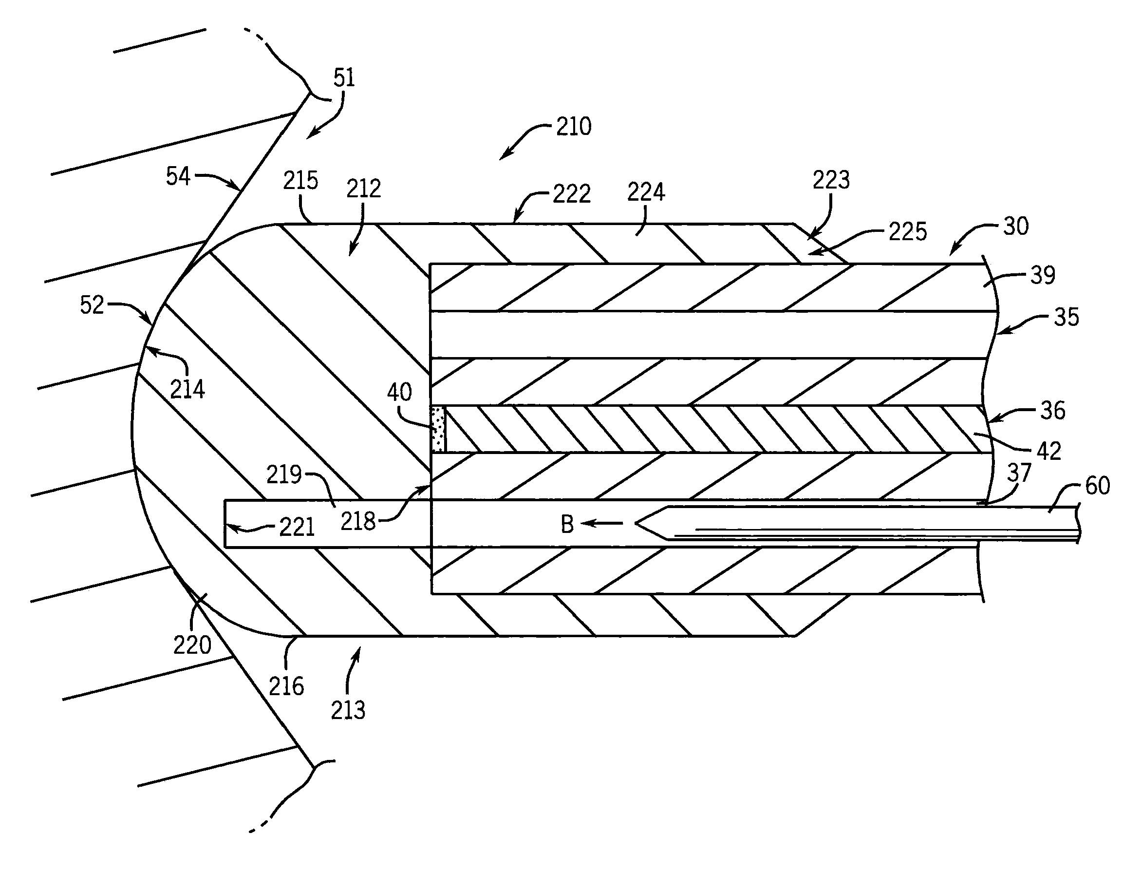
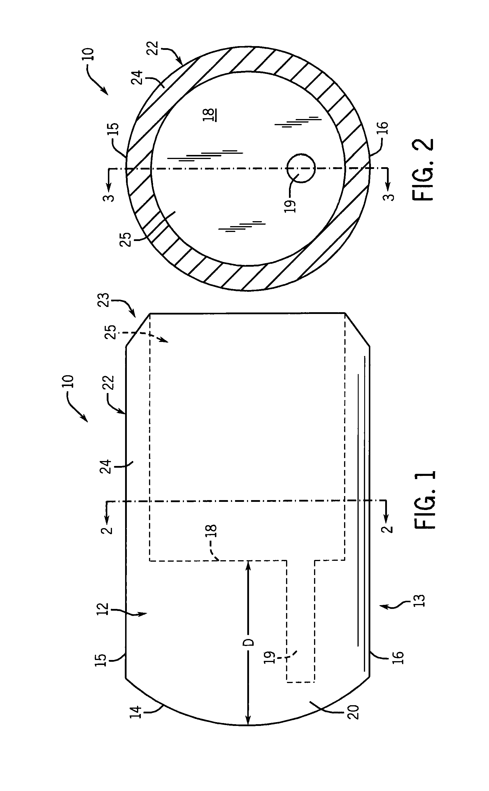
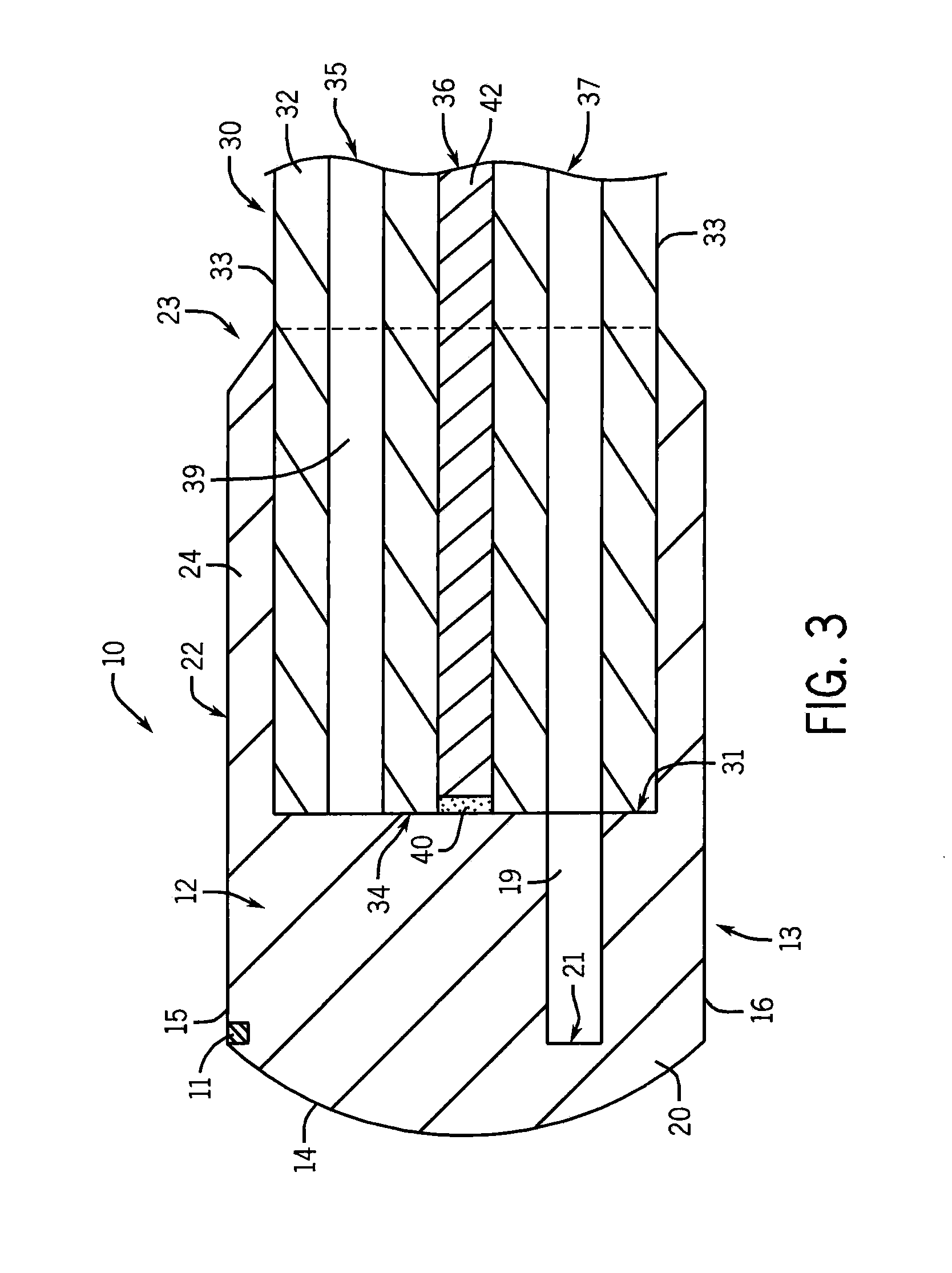
[0011]The optical coupler of the invention is used for visualization in opaque fluids or semisolids, and comprises a clear, soft, flexible gel coupled to the outer distal portion of any optical imaging device, such as an endoscope or a camera lens. When pressed in contact with the surface of an area to be viewed, the coupler creates an offset that allows clear visualization by mechanically displacing the opaque liquid, semisolids, or particulate matter. This displacement allows the optically clear coupler to come into contact with a surface of interest, thus producing an unobstructed view to the observer.
[0012]In a non-limiting medical embodiment, the coupler

Problems solved by technology

The ability to convert open surgeries to minimally invasive procedures has been made possible with video endoscopy, but is limited when blood or other fluids are in the field of view.
Other technologies (fluoroscopy, 3-D echo, MRI, etc.) currently are used to overcome the challenge of performing surgery in intravascular spaces, but each technology presents limitations.
Procedures are lengthy creating

Method used


Image

  • Optical coupler for an endoscope
  • Optical coupler for an endoscope
  • Optical coupler for an endoscope

Examples


example 1

[0127]A coupler in a shape similar to that of FIG. 4 was formed from Sylgard® 184 silicone elastomer available from Dow Corning Midland, Mich. USA. This silicone has an index of refraction of 1.43, and a durometer of about 80 on the Shore OO scale. A monopolar electro cauterization wire was pre molded into the coupler and wire pulled through the endoscope working channel of a Pentax EG3430 11.4 mm gastroscope. The wire was connected to a Bovie electro cauterization unit. The coupler was slipped over the distal end of the gastroscope. In the open chest of a sheep, the colonoscope was advanced in blood approaching an area to be electro coagulated and video images showed a yellow flame / spark from electrocautery with no smoke visible.

example 2

[0128]A coupler in a shape similar to that of FIG. 4 was formed from Sylgard® 184 silicone elastomer. The coupler was attached to the end of a Pentax EG3430 11.4 mm gastroscope. Suitable video images were obtained in an electrocauterization procedure on a sheep esophagus wall.

example 3

[0129]A coupler in a shape similar to that of FIG. 4 was formed from Sylgard® 184 silicone elastomer. The coupler was attached to the end of a Pentax EG3430 11.4 mm gastroscope. Suitable video images were obtained in a sheep stomach.


PUM


Abstract

An optical coupler is disclosed with an attachment section for mounting at a distal end of an optical imaging device for visualizing a surface area covered with an opaque fluid and/or particulate matter. The coupler includes a visualization section at one end of the coupler that includes a proximal surface for engaging the distal end of the optical imaging device, an attachment section connected to and extending away from the visualization section, an outer surface spaced apart from the proximal surface, and may include a hollow instrument channel extending from the proximal surface toward the outer surface. This surface extends continuously from a first outer side boundary across to a second opposite outer side boundary of the visualization section. The visualization section can be formed from an elastic material capable of transmitting an optical image of the surface area. In one form, the material is a silicone gel or elastomer.

Description

CROSS-REFERENCES TO RELATED APPLICATIONS[0001]This application claims priority to U.S. Provisional Patent Application No. 61 / 443,546 filed Feb. 16, 2011, which is hereby incorporated by reference as if set forth in its entirety.STATEMENT REGARDING FEDERALLY SPONSORED RESEARCH[0002]Not Applicable.BACKGROUND OF THE INVENTION[0003]1. Field of the Invention[0004]This invention relates to an optical coupler for improved optical imaging of surfaces covered with opaque fluids, semisolid materials or particulate matter.[0005]2. Description of the Related Art[0006]The demand for minimally invasive surgery continues to grow. The ability to convert open surgeries to minimally invasive procedures has been made possible with video endoscopy, but is limited when blood or other fluids are in the field of view. Other technologies (fluoroscopy, 3-D echo, MRI, etc.) currently are used to overcome the challenge of performing surgery in intravascular spaces, but each technology presents limitations.[00...

Claims


Application Information

Patent Timeline
IPC IPC(8): A61B1/018A61B1/07
CPCA61B1/00096A61B1/00101A61B1/00137A61B1/00066A61B2017/00296A61B1/053A61B1/07A61B17/00234A61B17/068A61B1/00126A61B1/00087A61B1/00103A61B1/018G02B23/2423G02B23/2484
Inventor TITUS, JAMES SIDNEY
Owner THE GENERAL HOSPITAL CORP
Why Eureka
Try Eureka