Wavelength selective optical couplers

a selective optical coupler and wavelength technology, applied in multiplex communication, manufacturing tools, instruments, etc., can solve the problems of complicated bulk optic components, difficult to gain access to this reflected mode in a power efficient manner, and introduce a loss of 1 db or more in the circulator

Inactive Publication Date: 2001-09-18
ARROYO OPTICS
View PDF42 Cites 79 Cited by
  • Summary
  • Abstract
  • Description
  • Claims
  • Application Information

AI Technical Summary

Benefits of technology

Our invention achieves both optical filtering and splitting more reliably and efficiently by using an asymmetric coupler in which an index of refraction grating is impressed within the coupling region. This device is hereafter referred to as a grating assisted mode coupler. We eliminate undesired leakage of optical energy between waveguides by using dissimilar waveguides. We increase the grating coupling strength by merging or joining the two waveguides together into a single waveguide at the coupler waist. We significantly increase the separation between the backreflected and coupled wavelengths to improve the bandpass characteristics of the device by strongly fusing or merging the adjacent waveguides.
An important feature of the index of refraction grating is that it possesses transverse asymmetry, because it allows optical energy to be transfered between orthogonal or independent optical modes. That is, the index of refraction grating has a unique spatial distribution that enables one optical mode to be coupled to an orthogonal optical mode efficiently.

Problems solved by technology

The maximum allowable angular offset of the grating fringes with the longitudinal axis is generally less than 1 degree. Furthermore, to gain access to this reflected mode in a power efficient manner is difficult, because the wave is reflected backwards within the same fiber.
This circulator introduces an insertion loss of 1 dB or more and involves complicated bulk optic components.
This results in poor isolation of the optical signals traveling through the two waveguides, because optical power leaks from one fiber to the other.
However, this device used a reflection grating etched in a thin surface layer on one of the polished fibers, dramatically reducing the coupling strength of the grating.
A serious drawback of this device is that the wavelength for which light is backwards coupled into the adjacent fiber is very close to the wavelength for which light is backreflected within the original fiber (about 1 nm).
This leads to undesirable pass-band characteristics that are ill suited for add / drop devices that are designed to add or drop only one wavelength.
The separation between the backreflected and backwards coupled wavelengths is impractically small for the all-fiber, grating assisted directional coupler approaches of the prior art.
This device relies on the precisely controlled phase difference between two interferometer arms and is highly sensitive to environmental fluctuations and manufacturing variations.
Therefore, it is uncertain whether this device will be able to meet the demanding reliability requirements for telecommunications components.
The conventional grating assisted directional coupler suffers from both a relatively low coupling strength and small wavelength separation of back-reflected and backwards coupled light These problems arise because the two coupled optical waveguides remain physically separate and the light remains guided primarily in the original cores.
Furthermore, the conventional grating assisted directional coupler suffers from the small difference in modal propagation constants present in these glass rather than air-clad waveguides.
As a consequence, the recording of fiber gratings in standard single mode optical fibers of diminished diameter results in dramatically reduced diffraction efficiency.

Method used


Image

  • Wavelength selective optical couplers
  • Wavelength selective optical couplers
  • Wavelength selective optical couplers

Examples


example 2

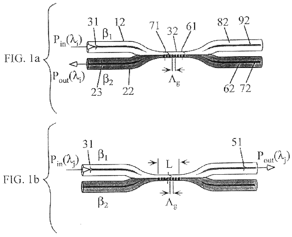
In another example of the coupler structure, a transverse asymmetry in the index grating is introduced by fusing two optical fibers 18, 22 which are dissimilar in the vicinity of the coupler and whose claddings 88, 62 are both photosensitive, as in FIG. 10. By using two photosensitive cladding optical fibers, the efficiency of the grating in the coupler waist 38 will be higher. The shading of FIG. 10a represents the degree of photosensitivity, or more particularly the degree of Ge, Ge / B, Ce, or P doping in the silica host. The coupler waist is of sufficiently small diameter that the cores 92, 72 no longer confine the mode, and the waveguiding properties are dictated primarily by the tapered cladding and the material of lower index (typically air) surrounding the coupler waist 38. The coupler waist 38 is subjected to an interference pattern of actinic radiation 70 whose normal to the interference fringe planes is inclined relative to the longitudinal axis of the waveguide as an alter...

example 3

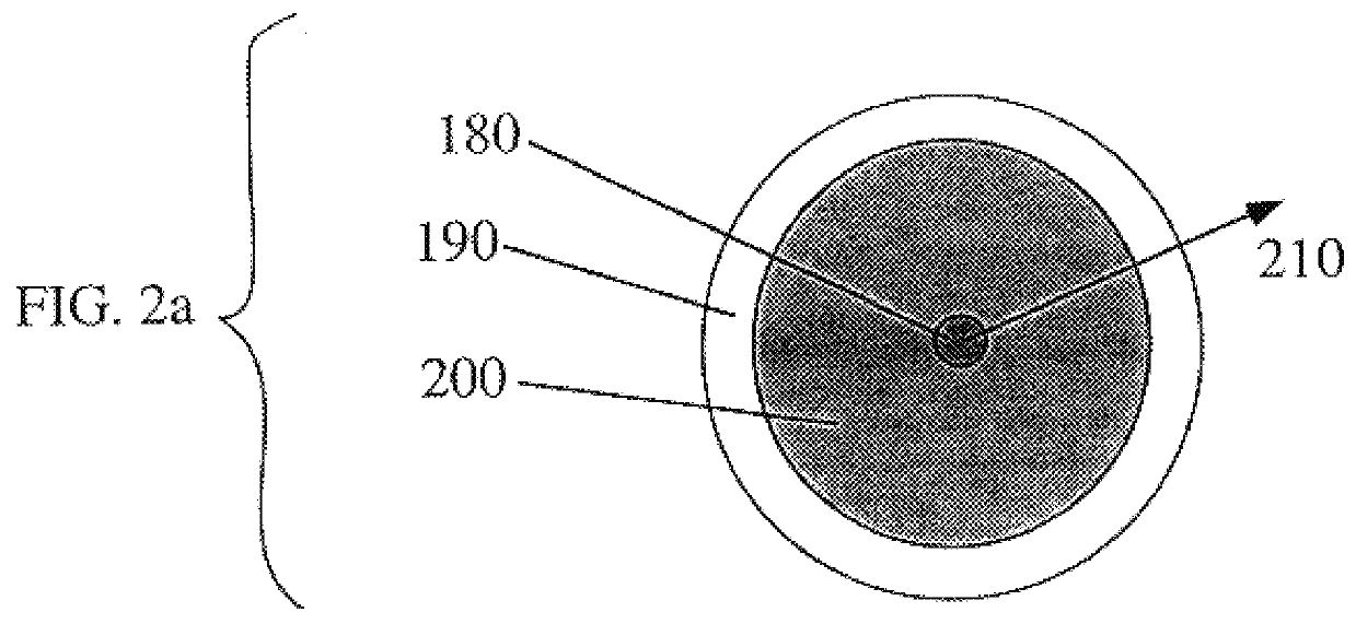
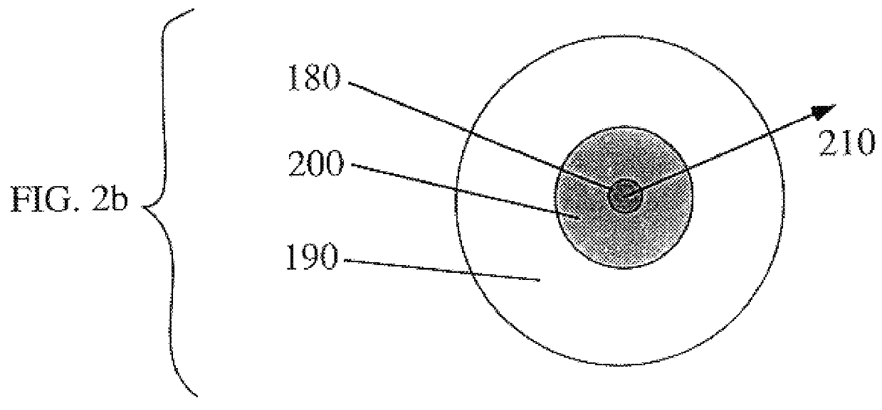
In yet another example, more than two locally dissimilar fibers are fused together to form a coupling region, as illustrated in FIG. 11. To impress a multiplicity of index of refraction gratings 122 within the coupler waist 11 using actinic illumination, at least one of the fibers of the fiber bundle 118, 120 possess a photosensitive cladding so that a grating can be recorded within the coupler. In the preferred embodiment, many of the fibers in the fiber bundle 118, 120 have photosensitive claddings.

example 4

In a different variant, the index modulation of the coupling region is impressed by chemical indiffusion, outdiffusion, or etching through a patterned photoresist 142 defining the grating 144, as illustrated in FIG. 12. This particular example illustrates the patterning of the gratings for an eight channel WDM multiplexer / demultiplexer 126 implemented on a planar waveguide circuit composed of silica on silicon 124. To impress the grating, Ti or Ge is indiffused into silica or HF acid can be used to etch silica according to the resist pattern. Note that these processing steps are particularly well suited for fabricating couplers on planar substrates, which lend themselves well to the integration of several devices on the same substrate. Planar substrate devices are described in detail in J. T. Boyd, ed., Integrated Optics--Devices and Applications, IEEE Press, LEOS Progress in Lasers and Electro-Optics Series, New York (1991). In one example, silica is deposited on silicon by flame h...


PUM

PropertyMeasurementUnit
insertion lossaaaaaaaaaa
wavelengthaaaaaaaaaa

Abstract

A wavelength selective optical fiber coupler having various applications in the field of optical communications is disclosed. The coupler is composed of dissimilar waveguides in close proximity. A light induced, permanent index of refraction grating is recorded in the coupler waist The grating filters and transfers energy within a particular range of wavelengths from a first waveguide to a second waveguide. Transversely asymmetric gratings provide an efficient means of energy transfer. The coupler can be used to combine or multiplex a plurality of lasers operating at slightly different wavelengths into a single fiber. Other embodiments such as a dispersion compensator and gain flattening filter are disclosed.

Description

The present invention relates to the communication of signals via optical fibers, and particularly to an optical fiber coupler and methods for making the same. More particularly, the invention relates to a wavelength selective optical coupler and other devices using a refractive index grating in a coupling region.DESCRIPTION OF RELATED ARTLow loss, wavelength selective couplers are important components for optical fiber communication networks based on wavelength division multiplexing (WDM). WDM enables an individual optical fiber to transmit several channels simultaneously, the channels being distinguished by their center wavelengths. An objective is to provide a precise wavelength selective coupler that is readily manufactured and possesses high efficiency and low loss. One technology to fabricate wavelength selective elements is based on recording an index of refraction grating in the core of an optical fiber. See, for instance, Hill et al., U.S. Pat. No. 4,474,427 (1984) and Glen...

Claims


Application Information

Patent Timeline
Patent Type & Authority Patents(United States)
IPC IPC(8): G02B6/12G02B6/34G02B6/28H04J14/02G02B6/293
CPCG02B6/02114G02B6/02133G02B6/02138G02B6/022G02B6/02204G02B6/12007G02B6/29334G02B6/29383G02B6/02085H04J14/0219G02B6/02109G02B6/02152G02B6/2835H04J14/0201H04J14/0206H04J14/0209H04J14/0213G02B6/021
Inventor KEWITSCH, ANTHONY S.RAKULJIC, GEORGE A.YARIV, AMNON
Owner ARROYO OPTICS
Why Eureka
Try Eureka