Anode gas stack start-up heater and purge gas generator

a technology of anode gas and generator, which is applied in the direction of electrochemical generators, cell components, cell component details, etc., can solve the problems of recuperative heat transfer, significant energy loss from hot gas exhaust, and deleterious stack heating process, so as to facilitate the heating of solid oxide fuel cell generators

a technology of anode gas and generator, which is applied in the direction of electrochemical generators, cell components, cell component details, etc., can solve the problems of recuperative heat transfer, significant energy loss from hot gas exhaust, and deleterious stack heating process, so as to facilitate the heating of solid oxide fuel cell generators

US20070275282A1Inactive Publication Date: 2007-11-29SIEMENS ENERGY INC

Image

  • Anode gas stack start-up heater and purge gas generator
  • Anode gas stack start-up heater and purge gas generator
  • Anode gas stack start-up heater and purge gas generator

Examples


Embodiment Construction

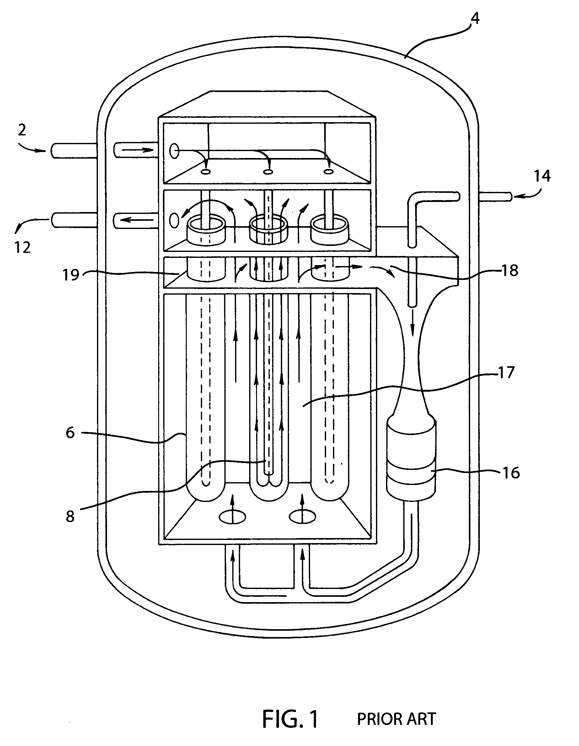
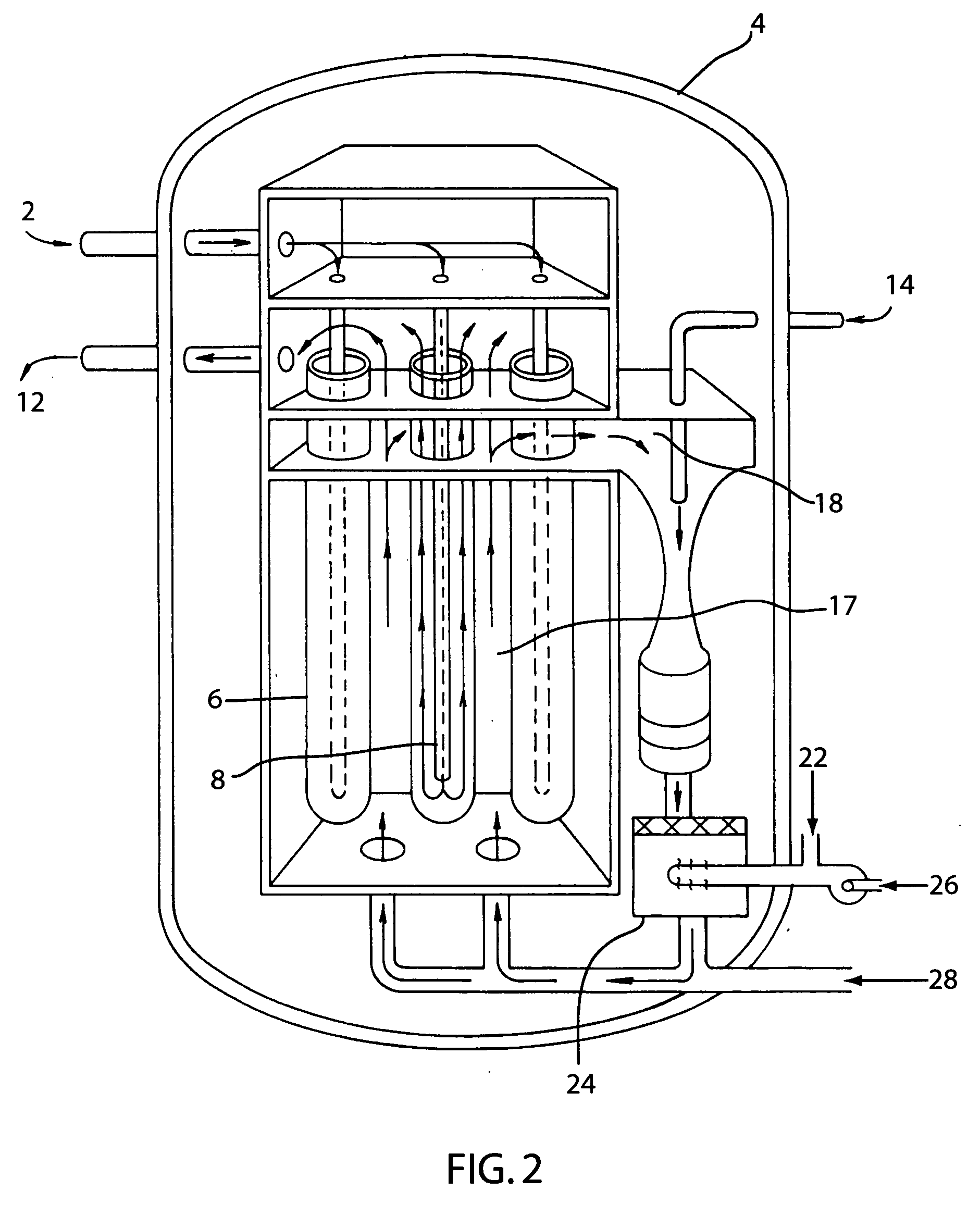
[0020]The present invention provides for an anode gas side heating during startup of a solid oxide fuel cell (SOFC) generator. The start-up heaters of the prior art used hot air blown into the air feed tubes to heat the seal-less design SOFC generators. Unfortunately, this heats the generator very slowly since the thermal conductivity through the parts of the generator where the air comes into contact with are poor thermal conductors. Moreover, the air passes back over its own feed tube before being exhausted, which transfers a significant portion of the heat back to the used gas before it is exhausted.

[0021]The present invention heats the SOFC generator by circulating heated anode side gas. As is known in the art, the anode gas flow path is the fuel flow path. During normal operation of a SOFC, the major portion of the anode gas flow is recirculated spent fuel gas (about ¾) with fresh fuel addition representing a minor portion. Therefore, when anode gas is heated prior to admission...


PUM

PropertyMeasurementUnit
temperatureaaaaaaaaaa

Abstract

In one embodiment the present invention provides for an anode side gas flow heater for a fuel cell generator that comprises a recirculating anode gas flow 28, at least one burner 24, and an energy source 22. The energy source heats the burner, the anode gas flow passes over the at least one burner and is heated, and the heated anode gas flow is then passed through the anode side of the fuel cell generator 4, where the fuel cell generator is heated.

Description

[0001]The U.S. Government has a paid-up license in this invention and the right in limited circumstances to require the patent owner to license others on reasonable terms as provided for by the terms of DE-FC26-97FT34139 awarded by DOE.FIELD OF THE INVENTION[0002]The field of the invention relates to fuel cells, and more specifically to the heating of a fuel cell stack.BACKGROUND[0003]The temperature of SOFC Fuel cell stacks must be at least 600° C., and typically 750-1000° C., for operation. In order to heat the stack, to operating temperature, the present technique is to force heated air over the cathode side of the fuel cell using an air blower. The air is heated using an electric heater or duct burner in the process air flow path between the blower and the stack. To avoid excessive thermal stresses in the fuel cells, the temperature difference between entering air and a measure of stack average temperature is controlled. For tubular SOFC stacks, the maximum temperature differenc...

Claims


Application Information

Patent Timeline
29 Nov 2007
Publication
US20070275282A1
IPC
H01M8/04; H01M8/12
CPC
H01M8/04022; H01M8/04097; Y02E60/50; H01M8/04268; H01M8/243; H01M8/04231; Y10T137/6443; H01M8/2457
Inventors
VEYO, STEPHEN E.; GEORGE, RAYMOND A.