System for guiding a medical instrument in a patient body
a technology for guiding a medical instrument and a patient body, applied in the field of medical systems, can solve the problems of complicating the interventional procedure, narrow viewing field, low resolution, etc., and achieve the effect of improving the visibility of the medical instrument and its surrounding anatomy
- Summary
- Abstract
- Description
- Claims
- Application Information
AI Technical Summary
Benefits of technology
Problems solved by technology
Method used
Image
Examples
first embodiment
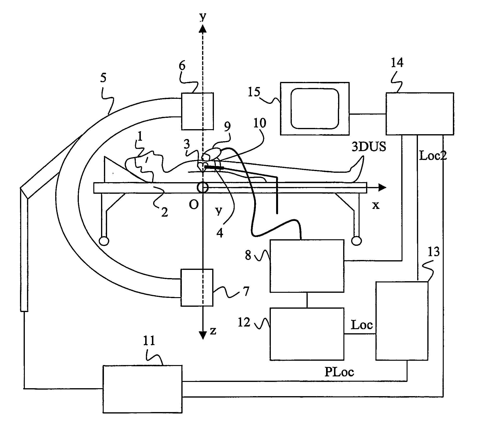
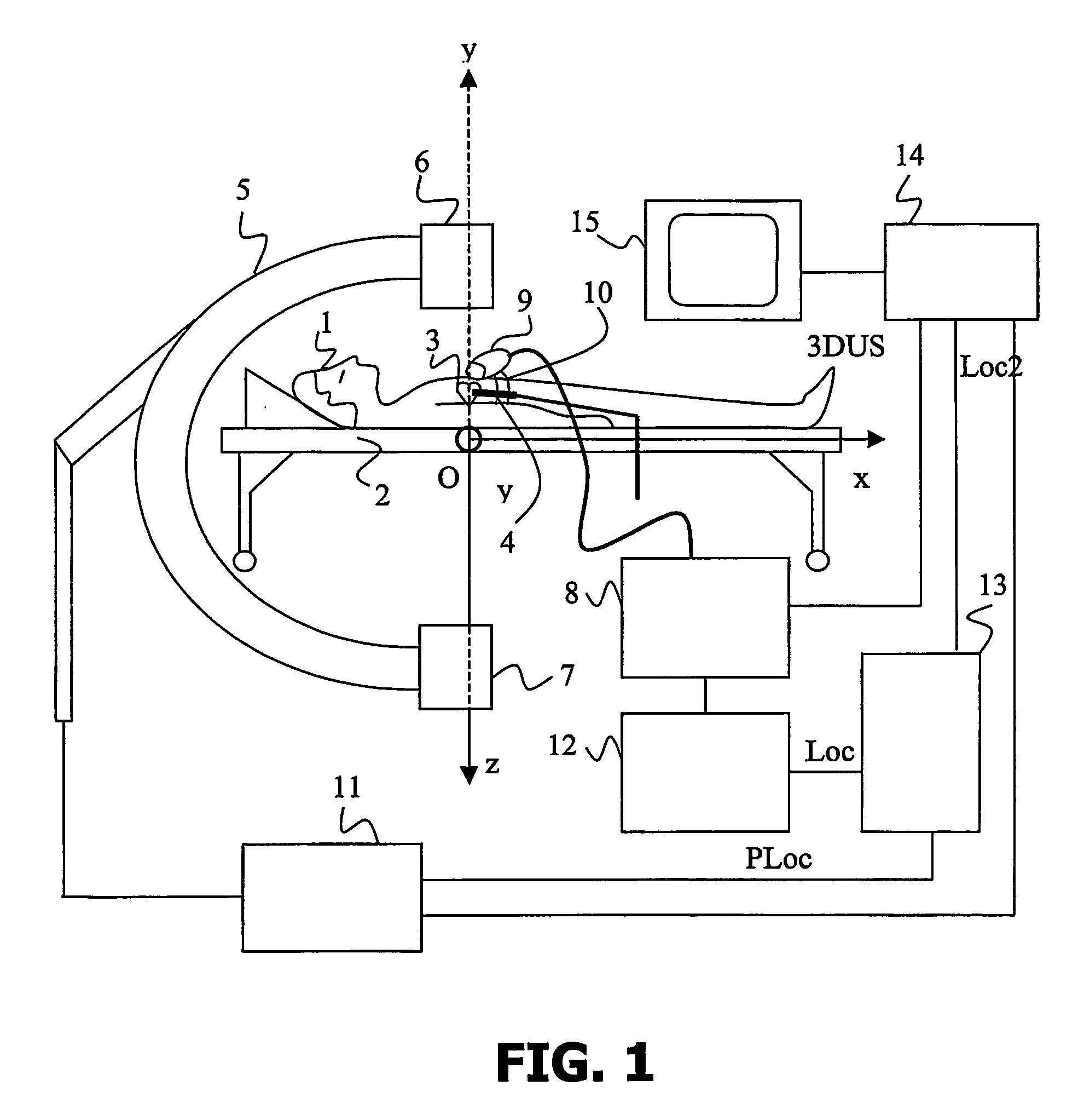
[0063] In the invention, the region of interest of the medical instrument is included into the reference plane 30, 33. Therefore, the ultrasound information contained in the region of interest corresponds to a 2D ultrasound view 41, which is obtained by sampling the 3D ultrasound data set over the reference plane 30, 33.
[0064] The bimodal representation is an image formed such that the intensity values of all the points of the 2D X-ray projection 40 which have a corresponding point in the 2D ultrasound view 41 are combined. Such a combination is for instance defined by a scalar function f of a first intensity value I1 of a point of the 2D X-Ray image 40 and a second intensity value I2 of the corresponding point in the 2D ultrasound view 41. Such a scalar function f provides an intensity value I, for instance, by implementing an alpha-blending technique, which is well-known to those skilled in the art, in the following way:
I=ƒ(I1,I2)=αI1+(1−α)I2
[0065] If α is equal to one, then the...
second embodiment
[0069] In the invention shown in FIG. 8, the system in accordance with the invention further comprises means for segmenting a wall tissue region, for instance the endocardiac wall 44 in the neigbourhood of the medical instrument 4. This is achieved by image processing techniques such as intensity value thresholding, since wall tissues like myocardium appear brighter than blood in ultrasound images.
[0070] Another possibility is to detect borders, for instance by using an active contour technique (also called “snake”). This technique, well known to those skilled in the art, firstly consists in defining an initial contour and secondly in making said initial contour evolve under the influence of internal and external forces. A final contour 46 is obtained. It is then possible to differentiate points located inside from points located outside the contour 46 and to only give to the outside points the intensity values of the corresponding points of the 2D ultrasound view 41. An advantage o...
third embodiment
[0071] In the invention schematically presented in FIG. 9, the system in accordance with the invention further comprises means for generating a volume rendered image 51 of the defined region of interest 35. In the present example, the region of interest 35 is a slab 50. The volume rendered image 51 is obtained by integrating the 3D ultrasound data in accordance with a direction, for instance the direction of orientation of the X-Ray acquisition means, as illustrated by the cylinder 52. Said volume rendered image 51 is used instead of the 2D ultrasound view 41 and combined with the 2D X-ray image 40 for generating a bimodal representation 53 in a similar way as previously described. An advantage of this third approach is to provide a perspective view of the neighbourhood of the medical instrument 4, which are for instance the heart cavities.
[0072] It should be noted that the generation means 14 could inversely generate a bimodal representation on the basis of the 3D ultrasound data s...
PUM
 Abstract
Description
Claims
Application Information
 - R&D
- Intellectual Property
- Life Sciences
- Materials
- Tech Scout
- Unparalleled Data Quality
- Higher Quality Content
- 60% Fewer Hallucinations
Browse by: Latest US Patents, China's latest patents, Technical Efficacy Thesaurus, Application Domain, Technology Topic, Popular Technical Reports.
© 2025 PatSnap. All rights reserved.Legal|Privacy policy|Modern Slavery Act Transparency Statement|Sitemap|About US| Contact US: help@patsnap.com


