Construction element form and method of fabricating same

Inactive Publication Date: 2007-11-29
SWANSON THOR
View PDF42 Cites 12 Cited by
  • Summary
  • Abstract
  • Description
  • Claims
  • Application Information

AI Technical Summary

Benefits of technology

[0003]Briefly described, the present invention, in a preferred embodiment thereof, comprises an improved form for fabricating concrete, lightweight concrete, or other poured construction material panels, and an improved method for fabricating such a form. The form, generally, depending on the construction panel for which it is intended is comprised of metal or other suitably strong frame members which are machined to precise tolerances utilizing computer controlled cutting machines such as lasers, water jet, or other similar precision computer controlled cutting machinery. These frame members are cut from structural tubing of suitable precise dimensions in order to negate the need for additional reinforcement to resist the substantial pressures created by the concrete or other construction material poured into the form. The form also includes metal plates which are precision cut, similarly using computer controlled precision cutting machines such as lasers, plasma, water jet, or other precision machining methods for cutting plate to close dimensional tolerances that will be familiar to those skilled in the art of metal fabrication and machining. These metal plates and metal tubing frames are precision machined in such a manner that they can be assembled quickly and efficiently onsite utilizing standard assembly methods of bolts and nuts, tabs, slots and pins, and other such standard methods of assembling metal elements. Some elements which require permanent assembly may be welded together rather than utilizing other attachment means. Some of the metal plates are machined in such a way as to fit together precisely forming a matrix for the bed of the form, therefore allowing disassembly of the form into smaller and more portable sections, yet allowing tight enough joints in the matrix to prevent the pourable construction material from leaking through the form. The sides of the form are precisely cut to allow them to be attached to the bed of the form and be held in place by easily removable pins. The side elements are comprised of plate which is reinforced with structural tubing in order to resist the pressure of the construction material, and to allow the attachment of formed plate elements to be removably attached to the interior of the side of the form in order to create a lap or rabbet joint in the finished construction panel for fitting one panel

Problems solved by technology

This process is wasteful of both time and materials, and has the further disadvantage of lacking precision, and detail for all but the most basic kinds of construction elements.
Where metal forms have been used, they have been made utilizing methods which limit the precision and detail required for the versatility needed in a complete

Method used


Image

  • Construction element form and method of fabricating same
  • Construction element form and method of fabricating same
  • Construction element form and method of fabricating same

Examples


Embodiment Construction

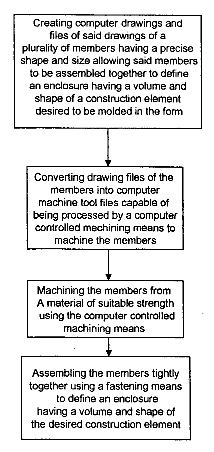
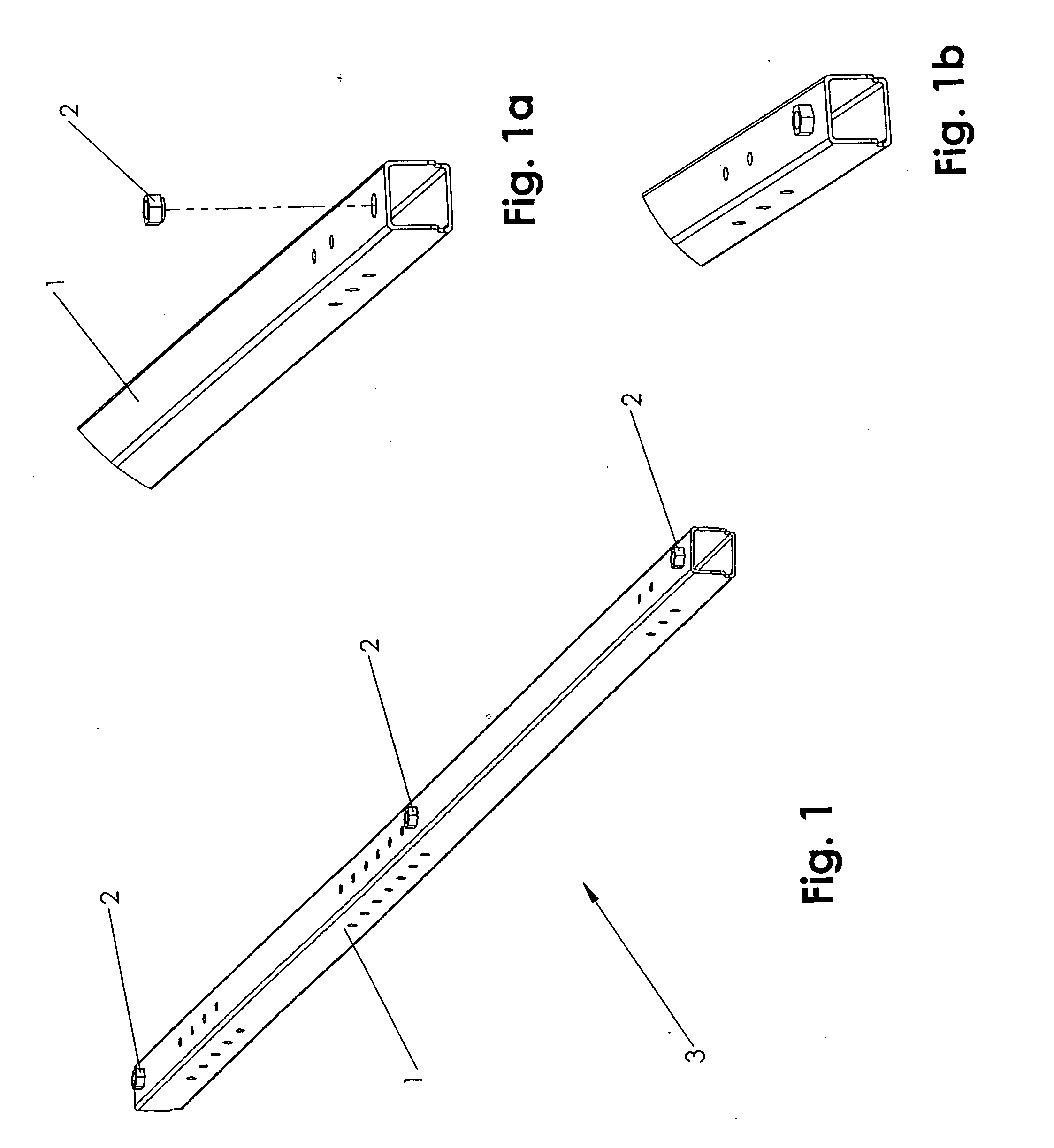
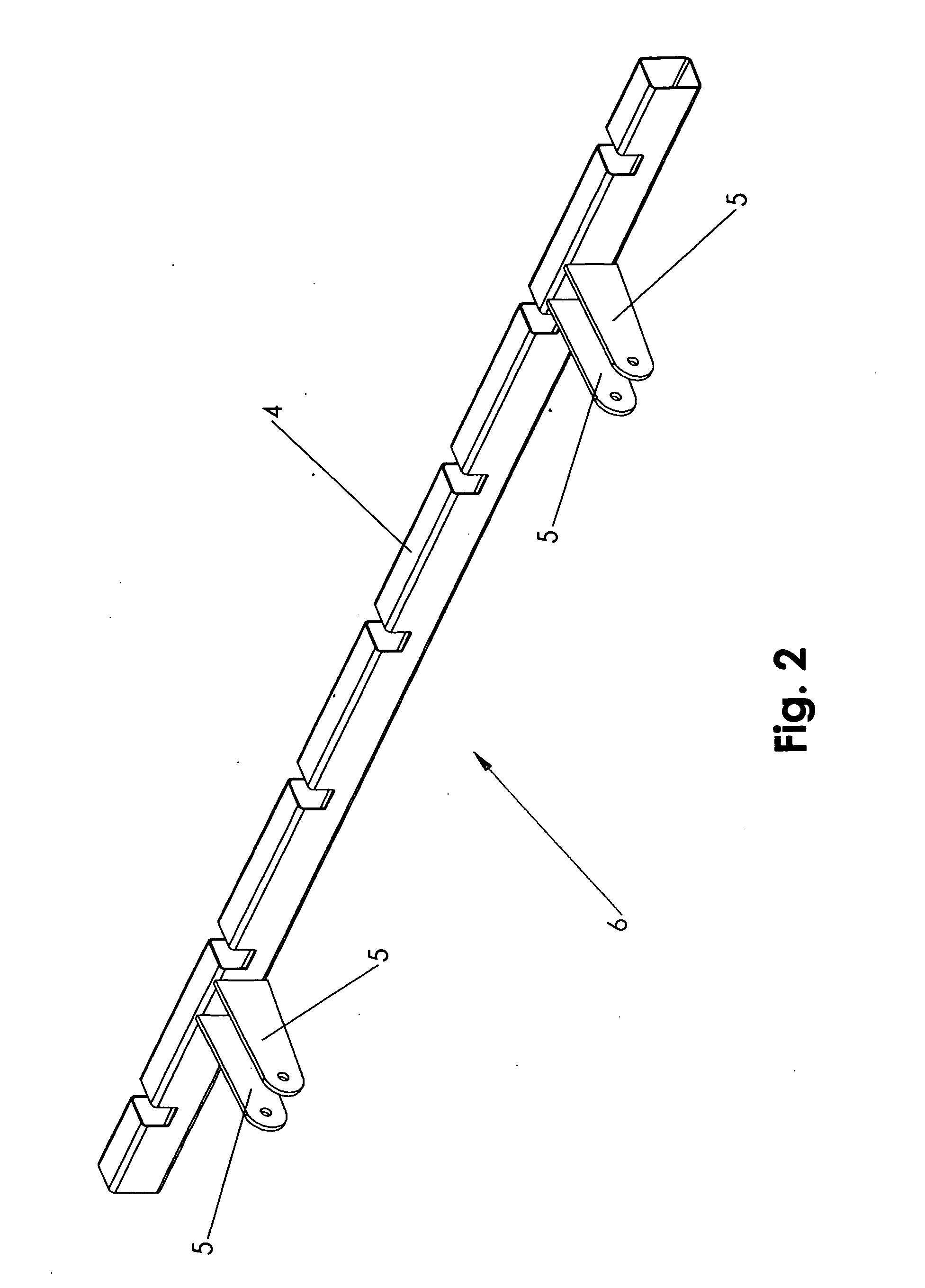
[0048]Referring now in more detail to the drawings, in which like reference numerals refer to like parts throughout the several views, FIG. 26 illustrates a first preferred embodiment of a construction panel form for a wall section. The form 117 includes a combination of many individual members using precision machined interlocking members, along with symmetrically interchangeable positional members, forming an enclosure, to define an area and volume precisely, and which can be disassembled for portability, reassembled rapidly, poured onsite, de-molded, and reconfigured quickly for another pouring, and be re-used in the same or different configuration many times over, all as is described in this specification. The use of computer controlled machining such as computer controlled laser machining, computer controlled water jet machining, computer controlled plasma machining, or similar cutting technologies, familiar to one skilled in the art, to machine the individual members of the fo...


PUM

PropertyMeasurementUnit
Weightaaaaaaaaaa
Sizeaaaaaaaaaa
Volumeaaaaaaaaaa

Abstract

A portable and re-usable form for molding construction panels, and a method for fabricating such a form, including, but not limited to, exterior and interior wall panels, columns, and roof panels is provided. The form includes a frame made from frame members which are precision fitted together utilizing corresponding tabs and slots machined into the frame members and held together with bolts or pins. Additional frame members may be positioned inside of the form to provide spaces for window or door frame installation and electrical conduits. A patterned liner may be placed into the form to produce a pattern on the surface of the construction panel. The form may be assembled at a job site and filled with light weight concrete, cellular concrete, concrete or other pourable construction material. When cured, the form is dis-assembled by removing the bolts or pins, freeing the construction panel which can be then placed into position and used to form a section of a structure.

Description

TECHNICAL FIELD[0001]This invention relates generally to building construction and more particularly to the fabrication of forms for the molding of precision construction panels that are positioned into place and attached to form a structure or parts of a structure.BACKGROUND[0002]Forms for the construction of buildings have been used for years. In general, these forms are built on site, filled with concrete, and, after the concrete cures, the form is disassembled, and discarded after use. This process is wasteful of both time and materials, and has the further disadvantage of lacking precision, and detail for all but the most basic kinds of construction elements. Where metal forms have been used, they have been made utilizing methods which limit the precision and detail required for the versatility needed in a complete construction system. Furthermore, these prior art forms do not allow for the integration of such elements as window and door frames, joint seals, electrical boxes an...

Claims


Application Information

Patent Timeline
IPC IPC(8): G06F19/00
CPCB28B7/0014E04G21/16B28B23/0025B28B7/346
Inventor SWANSON, THOR
Owner SWANSON THOR
Why Eureka
Try Eureka