
Method Of Locating A Cellular Terminal

Inactive Publication Date: 2007-12-06
TRISENT COMM
View PDF10 Cites 37 Cited by
  • Summary
  • Abstract
  • Description
  • Claims
  • Application Information

AI Technical Summary

Benefits of technology

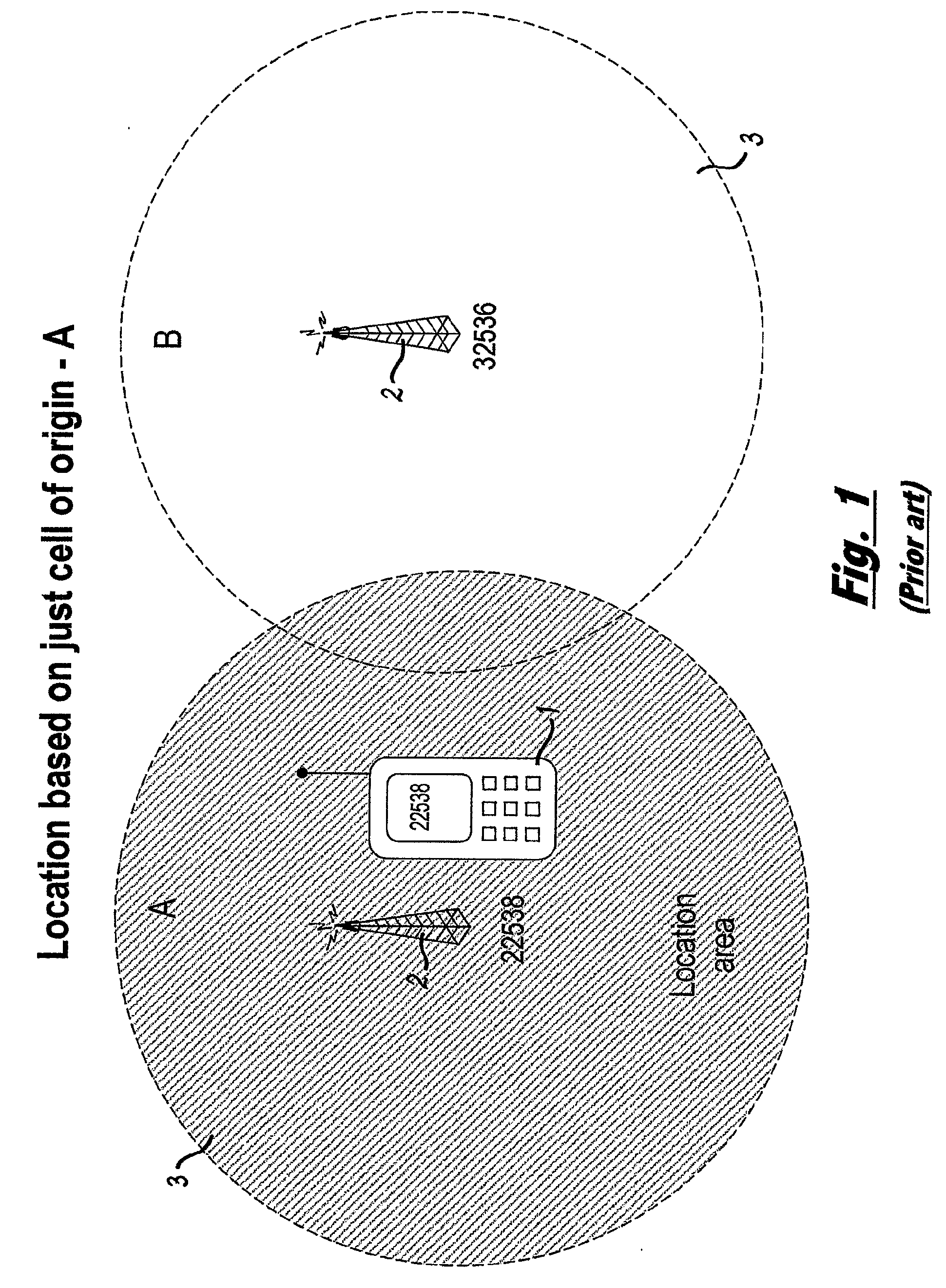
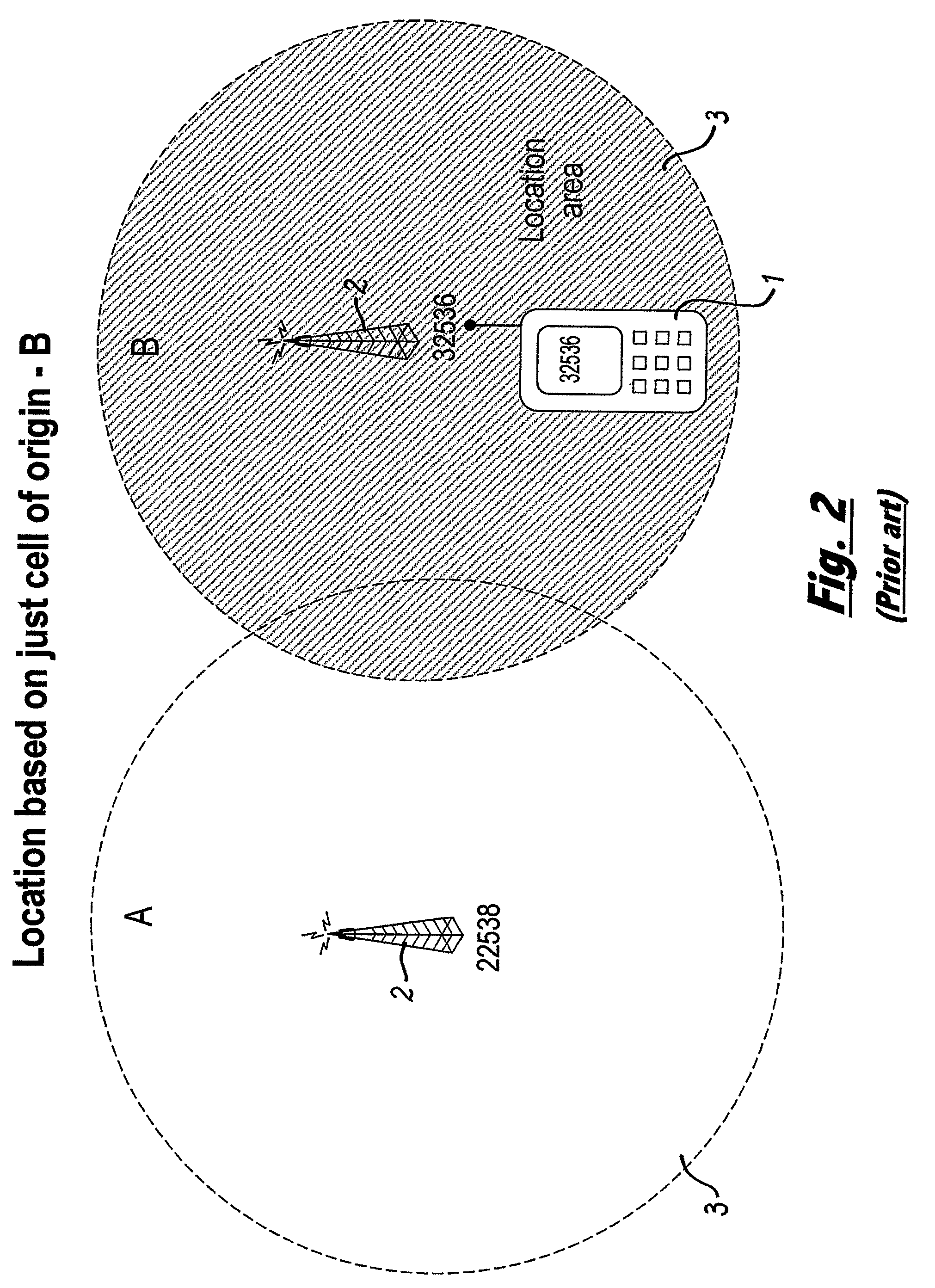
[0004] The accuracy of this technique is limited since it is largely dependent on the size of the cells 3 and so can generally only be approximated to within the cell radius. Furthermore, when employing the “cell of origin” methods there is often a latency experienced in the location information since it is normally sourced from the cellular network operator. The operator may provide only the last known cell location that in practice could be many minutes old. This latency reduces the accuracy and hence the value of the position information.
[0007] It is therefore an object of the present invention to provide a method of locating a cellular terminal that overcomes one or more of the aforementioned problems by providing a relatively simple, low-cost and accurate cellular terminal location system. SUMMARY OF INVENTION
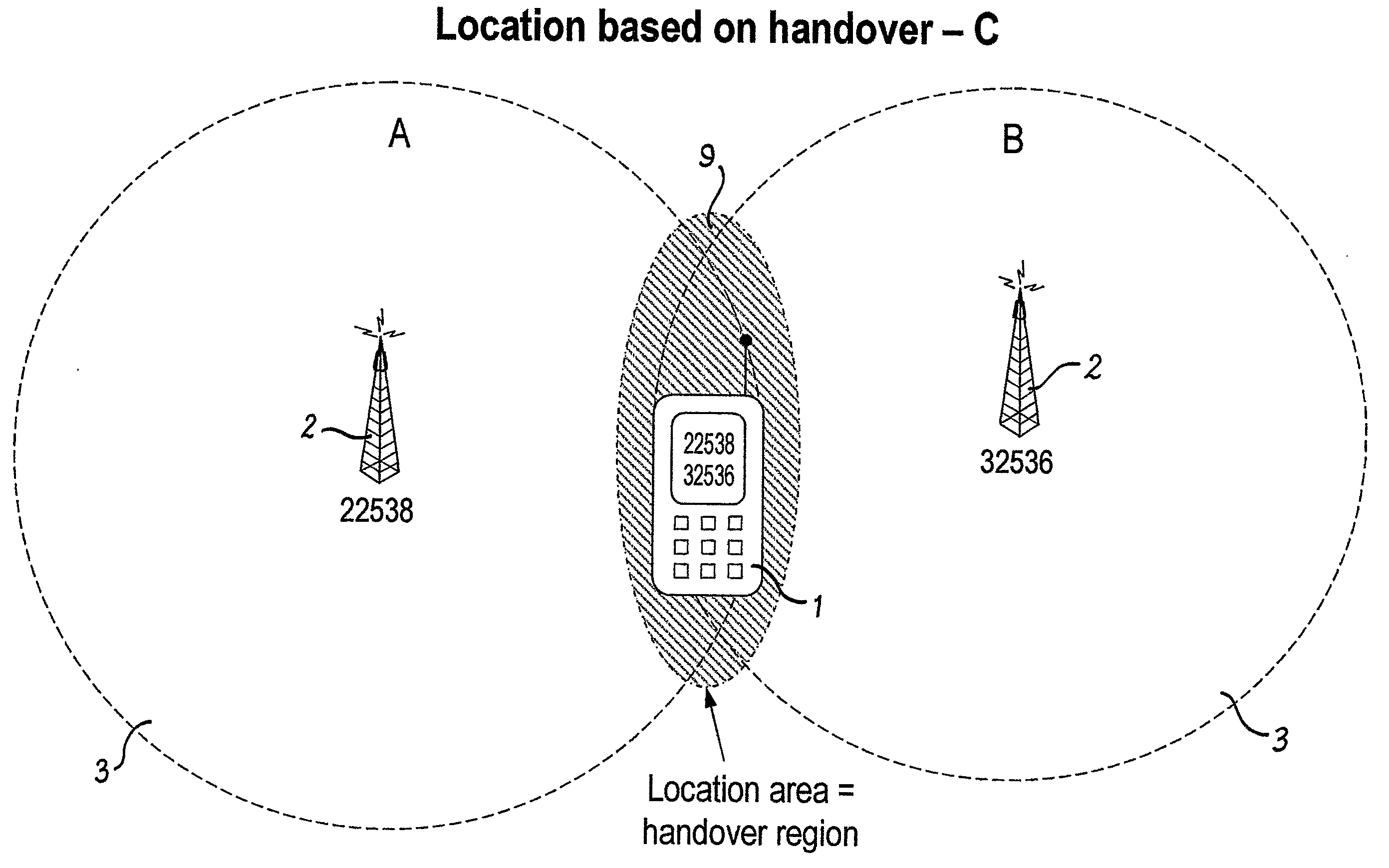
[0033] Optionally the recordal of the location of the one or more handover events allows the database to calculate higher order handover events so as to further increase the accuracy of the method of locating the cellular terminal.
[0035] Optionally the accuracy of the estimate of the location of the cellular terminal can be increased by employing knowledge of one or more handover events stored within the database between the first or second identified regions and a third identified region.
[0036] Optionally the accuracy of the estimate of the location of the cellular terminal can be increased by employing knowledge of the local geography stored within the database. For example, the knowledge of local transport routes can be employed to increase the accuracy of a cellular terminal recorded as travelling with a velocity greater that a typical walking speed of a cellular terminal user.

Problems solved by technology

The accuracy of this technique is limited since it is largely dependent on the size of the cells 3 and so can generally only be approximated to within the cell radius.
Furthermore, when employing the “cell of origin” methods there is often a latency experienced in the location information since it is normally sourced from the cellular network operator.
This latency reduces the accuracy and hence the value of the position information.
GPS solutions are generally more accurate than “cell of origin” methods but are significantly more expensive and have restricted use when required to operate indoors.
However, triangulation methods require additional equipment, processing and communications within the network side or require measurements to be made using modified or specialised terminal equipment.

Method used


Image

  • Method Of Locating A Cellular Terminal
  • Method Of Locating A Cellular Terminal
  • Method Of Locating A Cellular Terminal

Examples


Embodiment Construction

[0078] A first embodiment of a method of locating a cellular terminal 1, in accordance with an aspect of the present invention, involves the execution of a software application within the cellular terminal 1 that allows the cellular terminal 1 to communicate with a central database 4 stored on a server 5.

[0079] From the schematic representation of FIG. 3 it can be seen that in practice the central database 4 comprises five separate databases 4a-e, namely: [0080] 1. A cell location database 4a that holds a record of cell IDs against physical location for the centre of that cell coverage. This information is used to calculate data for inclusion in the handover database; [0081] 2. A handover database 4b that is the main database used to provide location data. This database holds data for cell handover pairs (or triples or quads) and files physical locations against these; [0082] 3. A netlist database 4c that provides a record of how cells 3 are connected to each other, as defined by o...


PUM


Abstract

A method of locating and tracking a cellular terminal (1) is described. The method comprises the detection of one or more handover events that take place when the cellular terminal (1) moves between transmission regions (3) of a cellular terminal network provider. Information regarding the handover events is recorded within a database (4) so that the location of the cellular terminal (1) can be calculated. The calculation of the location of the cellular terminal (1) is achieved by either comparing the information with previously stored data or by extracting information regarding the location and geometry of the individual transmissions regions (3) such that a handover region (9) can be calculated. The precise location and area of the handover regions (9) takes account of various factors including power, time of flight of the transmitted signals and timing synchronization within transmission regions (3) and the effects of shadowing of the transmitted signals.

Description

[0001] This invention relates to a method of locating a cellular terminal and in particular to a method of locating a cellular terminal that employs the standard communication process between the cellular terminal and associated communication network transmitters. [0002] Conventional methods of locating a cellular terminal 1 known to those skilled in the art employ so called “cell of origin” techniques, presented schematically in FIG. 1. In particular FIG. 1 depicts two base stations 2 each with an associated cell 3 that represents the range of transmission of the particular base station 2. The geographical position of the base stations is recorded within the network server. [0003] Normal practice is for the cellular terminal 1 to “camp” or couple with one particular base station 2, this typically being the base station 2 with the strongest signal, which is normally the base station 2 located closest to the cellular terminal 1. The location of the centre of that cell 3 is then assum...

Claims


Application Information

Patent Timeline
IPC IPC(8): G01S5/02H04Q7/38G01S5/14H04W64/00
CPCH04W36/08H04W64/00H04W36/083
Inventor POVEY, GORDONBAND, IAN
Owner TRISENT COMM
Learn More