
Fuel cell charger interface with multiple voltage outputs for portable devices

a fuel cell charger and portable device technology, applied in the direction of electrochemical generators, secondary cell servicing/maintenance, transportation and packaging, etc., can solve the problem of longer runtime for a given amount of fuel, and achieve the effect of facilitating a fast powering of auxiliary converters

Inactive Publication Date: 2007-12-13
MTI MICROFUEL CELLS
View PDF33 Cites 19 Cited by
  • Summary
  • Abstract
  • Description
  • Claims
  • Application Information

AI Technical Summary

Benefits of technology

[0010]The interface bypasses the conversion step from the battery voltage to the respective subvoltages that was required in prior techniques. This realizes an efficiency not only in bypassing the second conversion step, but further the expected conversion efficiency from the fuel cell voltage via the interface is likely more efficient when converting to a final voltage which is nearer the initial fuel cell voltage, rather than first converting to an intermediate voltage with a large difference from the initial fuel cell voltage and then converting back to the final voltage.
[0011]In the invent that the power requirement of the application device exceeds the output ability of the fuel cell and interface (boost / buck switcher) an auxiliary switch or linear regulator connected to a battery can be used to supplement the fuel cell / interface power, without interruption of supply. According to one embodiment of the invention, only if additional power is needed will the auxiliary supply activate from the battery. The auxiliary supply from the battery will only source enough supplemental power to make up the difference between the full rated output power of the fuel cell interface combination and that which has been demanded by the load. This way, a secondary loss is either eliminated or lessened by the less frequent use of the auxiliary supply from the battery.
[0012]It is noted that the auxiliary supply is still needed on start up and during peak power draw. However, during on-going operations, the techniques of the present invention will provide a more efficient power supply when multiple voltages are required by the application device. This translates to a longer runtime for a given amount of fuel for the fuel cell.
[0014]The interface of the present invention can include an individual switching converter which could be boost, buck, or buckboost, or any combination of individual switching converters, connected to the fuel cell system to generate the individual voltage rails. Alternatively, to reduce the number of individual switching converters that are required in the interface, a single switching converter can be used in the interface, the output of which is connected to both the application device's internal rail(s) and to the battery through output switches. Only one output switch is on at a time and the fraction of time each is on is adjusted so that each voltage is at it's desired level. Accordingly, it is possible to generate the various voltages required while reducing the number of additional converters, and inductors, in the interface.
[0016]In accordance with a further aspect of the invention, the fuel cell and interface can maintain a pre-charge on the output side of the auxiliary battery converters, which may facilitate a fast powering of the auxiliary converter.

Problems solved by technology

This translates to a longer runtime for a given amount of fuel for the fuel cell.

Method used


Image

  • Fuel cell charger interface with multiple voltage outputs for portable devices
  • Fuel cell charger interface with multiple voltage outputs for portable devices
  • Fuel cell charger interface with multiple voltage outputs for portable devices

Examples


Embodiment Construction

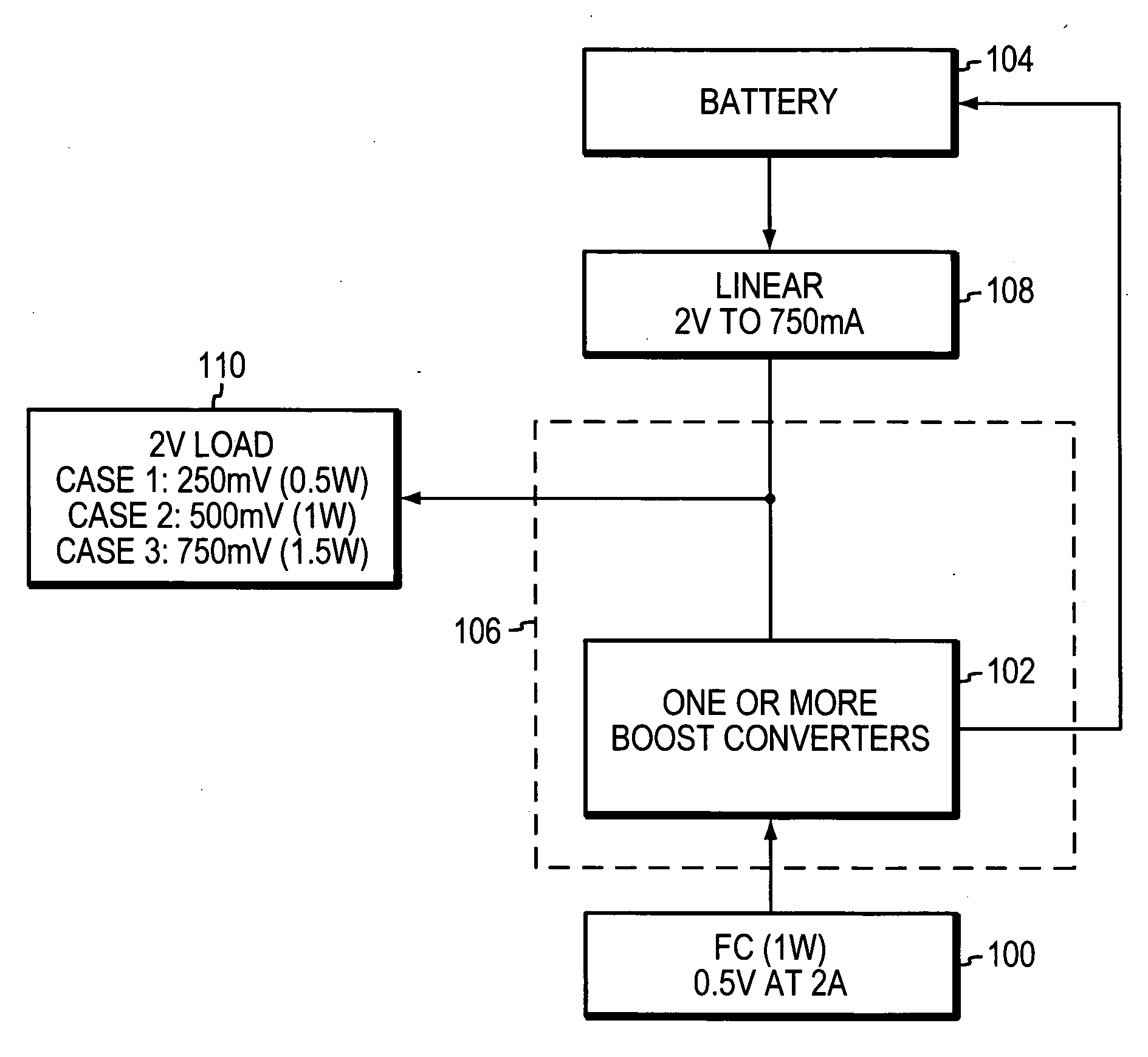
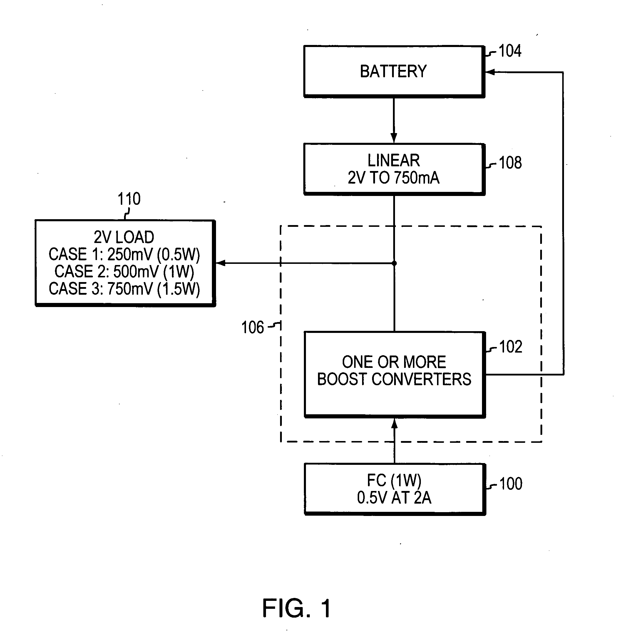
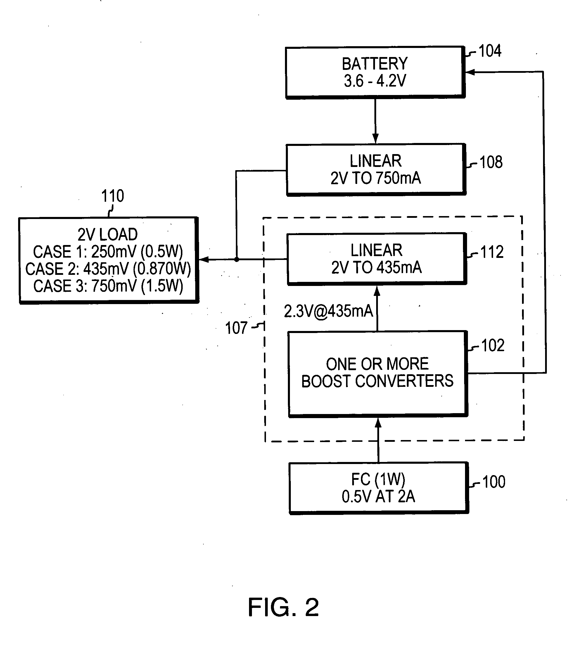
[0023]FIG. 1 illustrates a schematic block diagram of fuel cell interface combination in accordance with an illustrative embodiment of the present invention. More specifically, a fuel cell 100 may be any suitable fuel cell such as that described in commonly owned U.S. Pat. No. 6,981,877 of Ren et al., which issued on Jan. 3, 2006, which is presently incorporated herein by reference in its entirety. The fuel cell is coupled to a boost converter 102, which may be any suitable DC-DC converter readily available to those skilled in the art, or may be a DC-DC converter in accordance with commonly owned U.S. patent application Ser. No. 11 / 353,755 for a FUEL CELL BASED RECHARGEABLE POWER PACK SYSTEM AND ASSOCIATED METHODS FOR CONTROLLING SAME, of Leach et al., which was filed on Feb. 14, 2006, which is presently incorporated herein by reference in its entirety. The boost converter 102 forms part of an interface 106, which provides power directly to a load 110 in accordance with the inventio...


PUM

PropertyMeasurementUnit
voltageaaaaaaaaaa
voltageaaaaaaaaaa
output voltageaaaaaaaaaa

Abstract

A fuel cell-based powerpack for use with an electronic device that requires multiple voltages is provided. The power pack includes an interface between a direct oxidation fuel cell and one or more rechargeable batteries coupled to supply power to the electronic application device. The interface is connected to receive the output of the fuel cell and includes one or more DC-DC converters that not only boost power to said one or more batteries, but are further coupled to the electronic device such that the fuel cell can be used to directly provide one or more subvoltages, at required voltage rails, directly to said electronic device. The output voltage can also be linearly regulated if needed in a particular application.

Description

BACKGROUND OF THE INVENTION[0001]1. Field of the Invention[0002]This invention relates generally to power packs for electronic devices and more particularly, to systems for providing a fuel cell / battery hybrid power pack for an electronic device.[0003]2. Background Information[0004]There are many electronic devices in widespread use today including wireless phones, laptop computers, personal digital assistants (PDAs), walkie talkie's, mobile video systems and GPS navigation systems. These devices typically operate using a battery that is recharged when the device is not in use. A fuel cell can be coupled with the battery to provide a hybrid power pack for powering the electronic device.[0005]Many electronic devices require several voltage rails that are different than the battery output voltage. For example, in a wireless telephone, a 2.8 volt (v) voltage rail may be required for analog functionality and for the microphone and speakers of the phone. A 1.2 v voltage rail may be requi...

Claims


Application Information

Patent Timeline
Patent Type & Authority Applications(United States)
IPC IPC(8): H02J7/00H01M10/46H01M16/00
CPCH01M8/04619Y02B90/18H01M8/0488H01M8/0494H01M8/04947H01M8/1009H01M16/006H01M2250/30H02J1/10H02J7/0068H02J7/34H02J2001/004H02M2001/008H02M2001/009Y02E60/50H01M8/04626H02J2300/30H02M1/008H02M1/009Y02B90/10Y02E60/10
Inventor LEACH, DAVID H.MARVIN, RUSSELOPELA, PETER S.
Owner MTI MICROFUEL CELLS
Learn More