Current detection printed board, voltage detection printed board, current/voltage detection printed board, current/voltage detector, current detector and voltage detector

Inactive Publication Date: 2007-12-13
DAIHEN CORP
View PDF3 Cites 103 Cited by
  • Summary
  • Abstract
  • Description
  • Claims
  • Application Information

AI Technical Summary

Benefits of technology

[0041]An object of the invention is to provide a current transformer and a capacitor that can reduce a variation in current detection value or voltage detection value of individual detectors even though a plurality of detectors. Another object of the inven

Problems solved by technology

However, since relative magnetic permeability of a magnetic material used for the core is large, the self-resonant frequency becomes low.
That is, the detectable frequency band is limited.
However, there are many cases where the impedance matching device or the like is cramped.
Accordingly, it may be difficult to install the power transmission conductor 66 and the like simultaneously d

Method used


Image

  • Current detection printed board, voltage detection printed board, current/voltage detection printed board, current/voltage detector, current detector and voltage detector
  • Current detection printed board, voltage detection printed board, current/voltage detection printed board, current/voltage detector, current detector and voltage detector
  • Current detection printed board, voltage detection printed board, current/voltage detection printed board, current/voltage detector, current detector and voltage detector

Examples


Embodiment Construction

[0205]Hereinafter, the details of the invention will be described with reference to the drawings.

[0206](1) Current Detection Printed Board

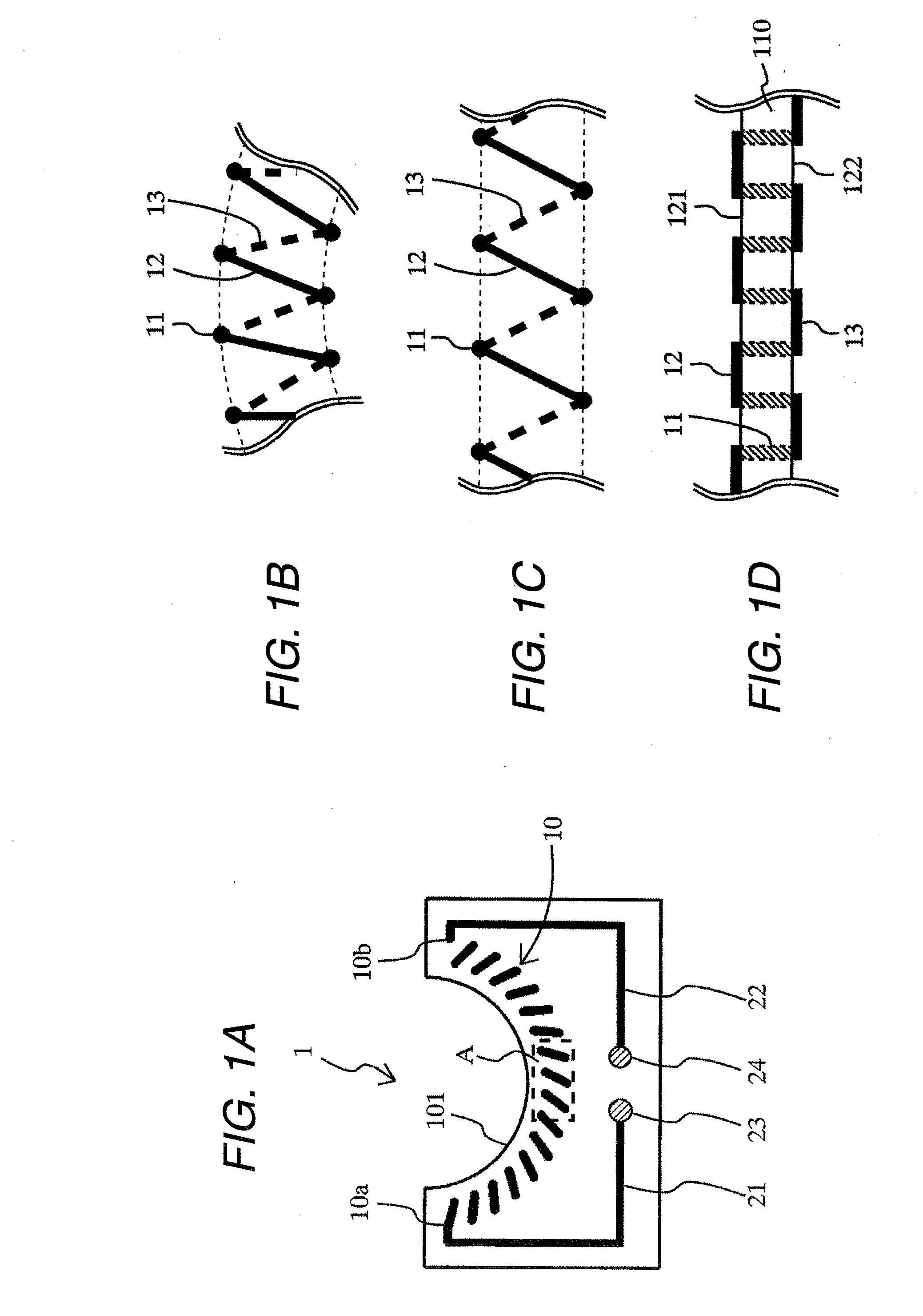
[0207]FIGS. 1A to 1D are diagrams showing an example of a current detection printed board 1 according to the invention.

[0208]Specifically, FIG. 1A is a plan view of the current detection printed board 1 (as viewed from the above). FIG. 1B is a schematic view of a portion (a portion A surrounded by a dotted line) of FIG. 1A on magnified scale (viewed from a direction of a cutout 101). FIG. 1C is a diagram showing linear expansion for simplification of FIG. 1B. FIG. 1D shows a wire of the current detection printed board 1 when FIG. 1C is viewed from the side. Moreover, as regards the wire shown in FIG. 1D, portions that are not typically viewed are shown in perspective view for explanation.

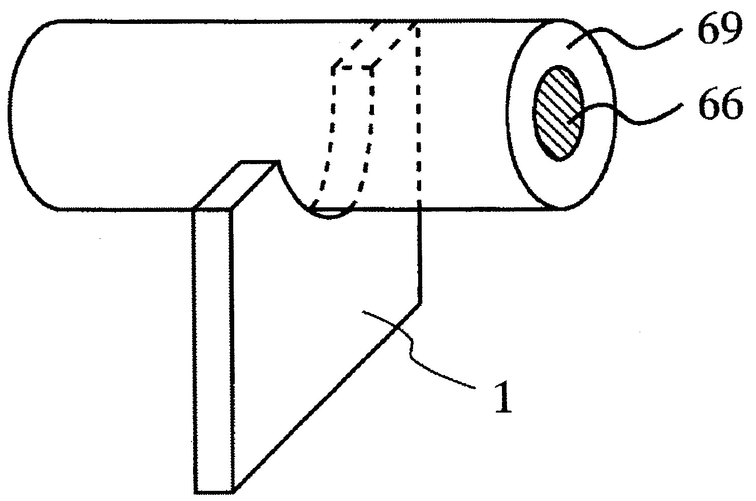
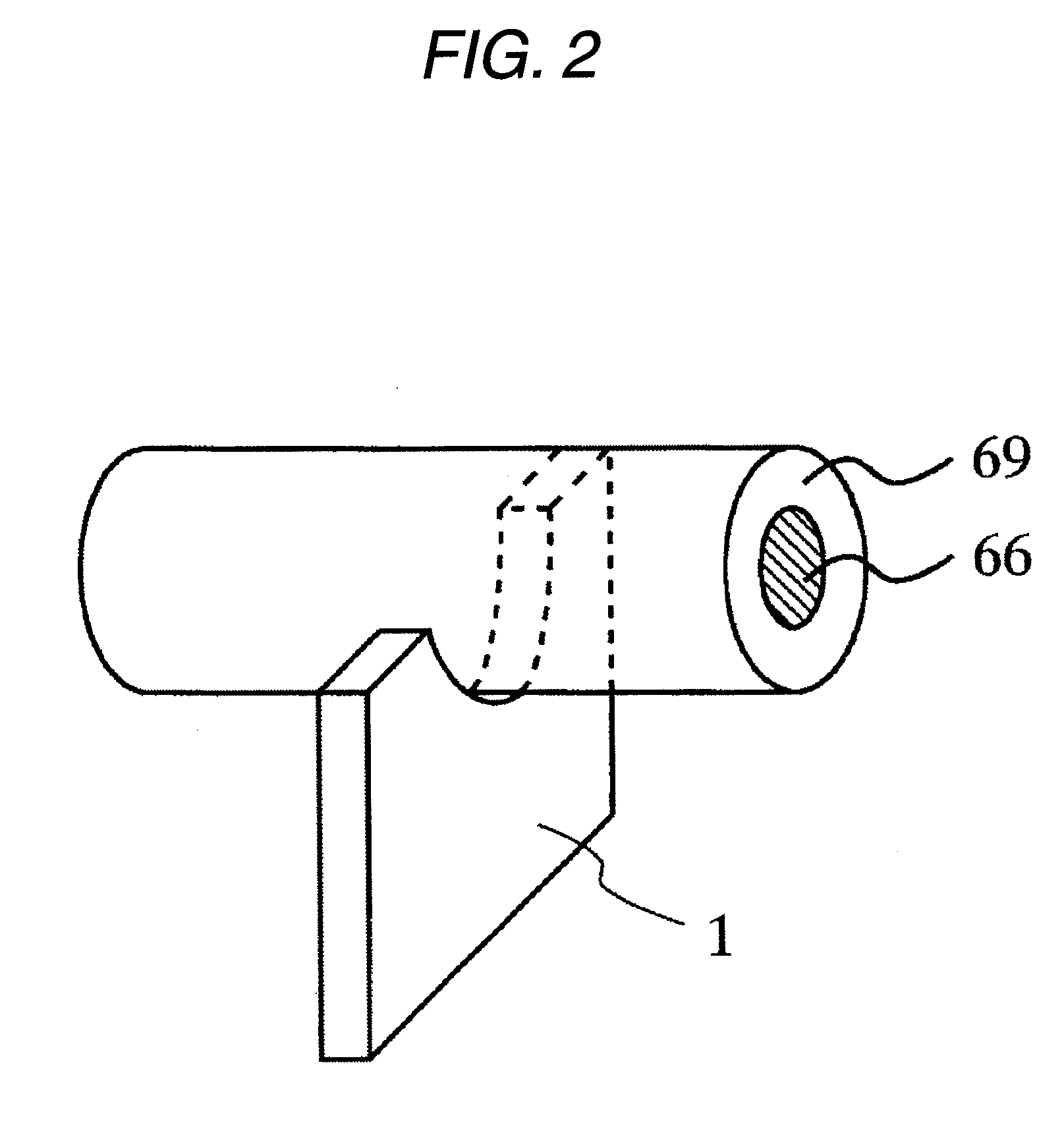
[0209]As shown in FIGS. 1A to 1D, the current detection printed board 1 is provided with a substantially semicircular cutout 101. A wire 10 (hereinafter, referred...


PUM


Abstract

A current detection printed board includes: a board having a penetration hole that penetrates the board; and at least one wire that is formed in a coiled shape having both ends by penetrating the board along the periphery of the penetration hole and alternately connecting a front surface layer and a rear surface layer of the board, wherein, when a conductor, in which an AC current flows, is disposed to pass through the inside of the penetration hole, a current flowing in the wire is output through electromagnetic induction.

Description

BACKGROUND OF THE INVENTION [0001]1. Technical Field of the Invention[0002]The present invention relates to a current detection printed board that is used to detect an alternating current flowing in a power transmission conductor used as an alternating current (AC) power transmission path, to a voltage detection printed board that is used to detect an AC voltage to be generated in the power transmission conductor, to a current / voltage detection printed board that is used to detect the alternating current (AC current) and the AC voltage, to a current / voltage detector to detect the alternating current and the AC voltage, and to a current detector and a voltage detector. In particular, the invention relates to a technology that uses high-frequency power as AC power.[0003]2. Description of the Related Art[0004]Like an impedance matching device or a high-frequency power supply device, there is known a device that detects AC power current and voltage and performs a control using the detec...

Claims


Application Information

Patent Timeline
IPC IPC(8): G01R33/00
CPCG01R15/142G01R15/18G01R15/181
Inventor IBUKI, YOSHIFUMIOMAE, SHUJIITO, HIDEO
Owner DAIHEN CORP
Why Eureka
Try Eureka