Sensors

a technology of sensors and pins, applied in the field of sensors, can solve the problems of inconvenient use, inconvenient touch screen devices, and so on, and achieve the effect of reducing pincushion errors and effective pincushion error correction

Inactive Publication Date: 2007-12-13
NOKIA CORP
View PDF8 Cites 4 Cited by
  • Summary
  • Abstract
  • Description
  • Claims
  • Application Information

AI Technical Summary

Benefits of technology

[0020]Alternatively, the non-conductive features can be generally V shaped. Advantageously two ends of each non-conductive feature can be located adjacent a common edge of the sensor. Two non-conductive features may be arranged one within the other and each of the two non-conductive features may have two ends adjacent a common edge of the sensor. These features allow one or more bounded conductive paths to be formed extending between opposite corners of a generally rectangular area, allowing finger detection at...

Problems solved by technology

Sensors such as that shown in FIG. 1 tend to suffer from so-called pincushion error.
Pincushion error results because of loss of charge to corners opposite the edge that the finger is near.
Since pincushion error produces location errors, it can be inconvenient for a user since the input device may register an input different to that intended.
This is particularly inconvenient with touch screen devices, although...

Method used


Image

  • Sensors
  • Sensors
  • Sensors

Examples


Embodiment Construction

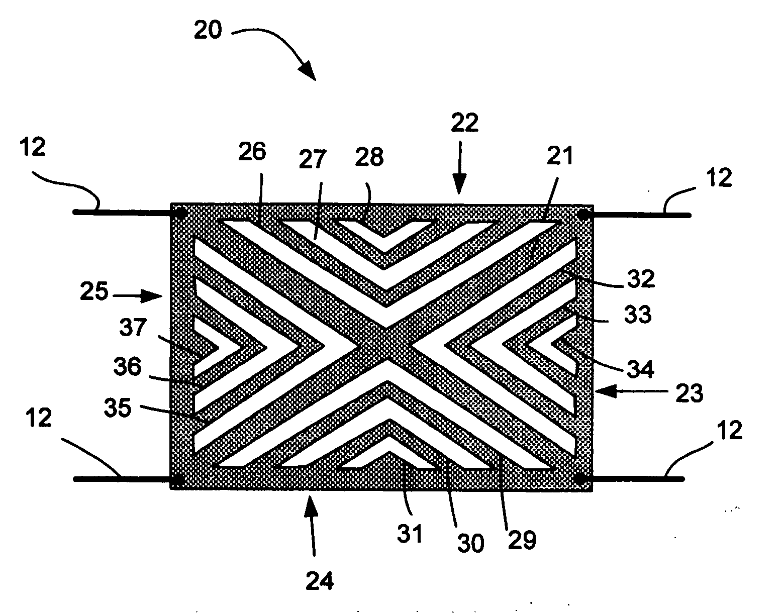
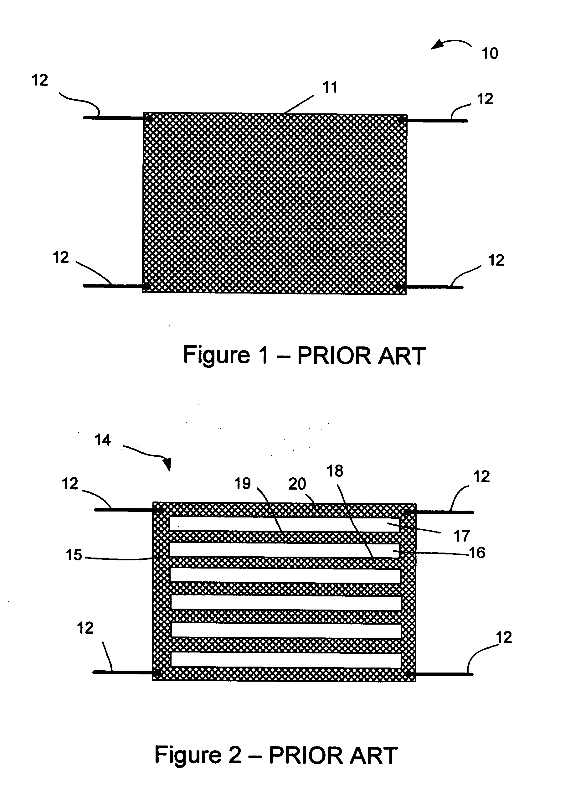
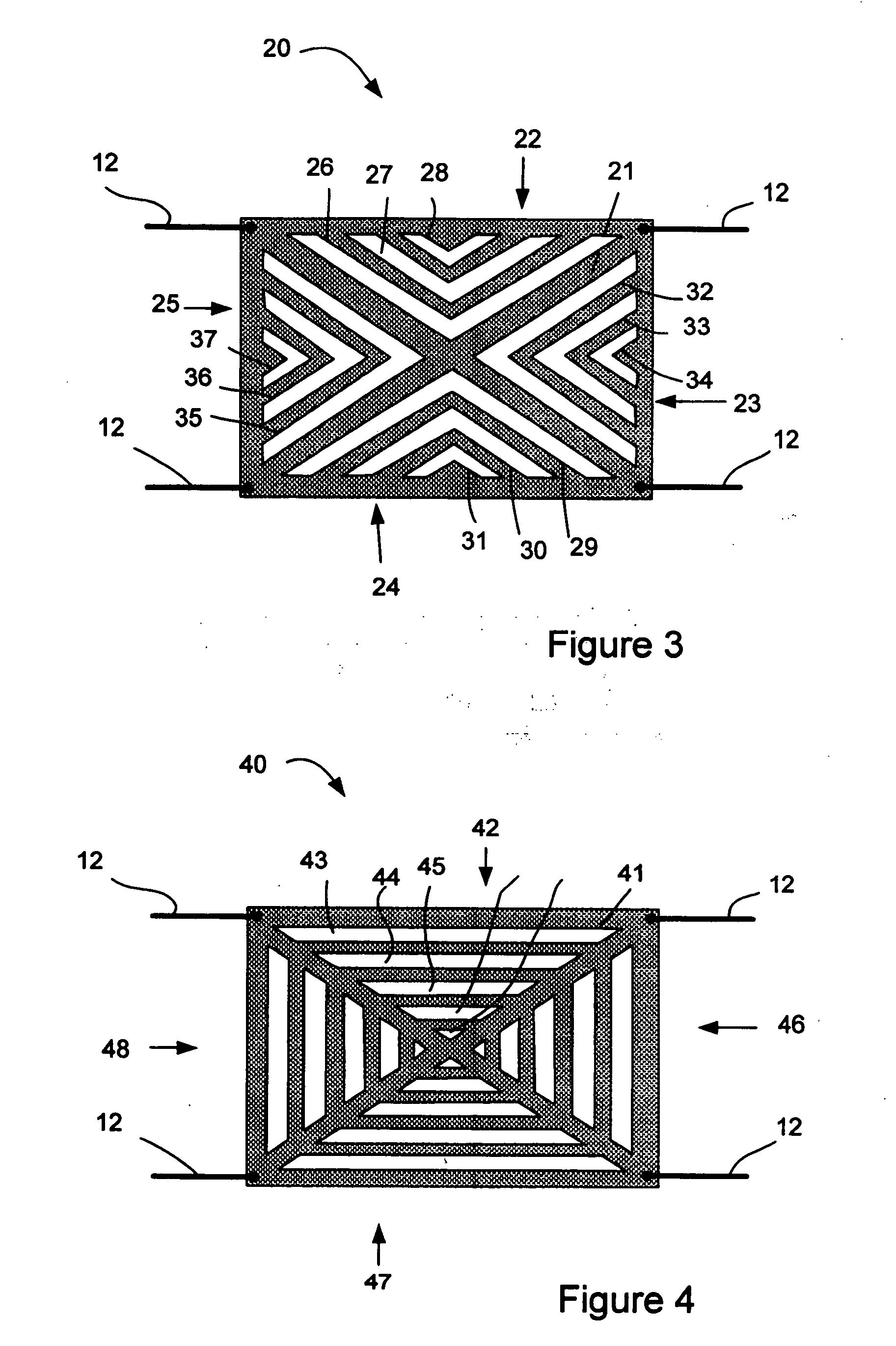
[0031]Referring to FIG. 3, a sensor 20 includes a conductive sheet 21. The conductive sheet 21 is formed of homogenised carbon paper, and thus is resistive. The resistive sheet 21 is in many ways the same as that illustrated in FIG. 1, and reference numeral 12 is again used to denote electrical connections at the corners of the sheet 21. The conductive sheet 21 is rectangular in shape. In this example, the conductive sheet 21 is approximately 40 mm by 50 mm. The conductive sheet 21 includes first to fourth edges 22 to 25.

[0032]Formed adjacent the first edge 22 are first to third features 26, 27 and 28. The features 26 to 28 are elongate apertures present in the conductive sheet 21. The features 26 to 28 thus constitute features having infinite resistance. Put another way, the features are non-conductive. Thus, an electrical charge requiring to be moved from one side of the feature to another side of the feature must move around an end of the feature.

[0033]The first feature 26 is a V...


PUM


Abstract

A sensor comprised includes a rectangular conductive sheet. Electrical connectors are connected at each corner of the sheet. A number of non-conductive features, e.g. apertures, are formed in this sheet. In one embodiment, V-shaped features extend from near the corners of the sheet towards the centre of the sheet and then turn towards an adjacent corner. Smaller V-shaped features reside in the area between the larger features and the closest edge of the sheet. In another embodiment, a spider web formation of conductive tracks or paths is provided. This provides hardware correction of pincushion error. It reduces or eliminates the need for software correction of pincushion error.

Description

FIELD OF THE INVENTION [0001]This invention relates to a sensor.BACKGROUND TO THE INVENTION [0002]Touch pads are well known, especially for portable devices such as laptop computers and mobile telephones. A touch pad is an input device, and includes a sensor and associated circuitry. When a user moves a stylus or finger to touch a part of the touch pad, that contact affects the sensor and is detected by the circuitry. There are various mechanisms for detecting the point of contact on the touch pad.[0003]One such mechanism is shown in FIG. 1. This sensor 10 utilises a rectangular conductive sheet 11 with an electrical connection 12 at each corner thereof. The conductive sheet 11 is made of homogenous graphite paper.[0004]The conductive sheet 11 is resistive. When a stylus or finger contacts the conductive sheet 11, the resistance at the contact point is changed, so the capacitance (and thus impedance) between two different ones of the electrical connections 12 is changed. To determin...

Claims


Application Information

Patent Timeline
IPC IPC(8): G06F3/041
CPCG06F2203/04113G06F3/045H03K17/96
Inventor KARHINIEMI, MARKOTUOVINEN, JUHANINOUSIAINEN, JARI
Owner NOKIA CORP
Why Eureka
Try Eureka