Reflecting apparatus

a technology of reflecting apparatus and mirror, which is applied in the field of reflecting apparatus, can solve the problems of unintended deformation of the mirror, deformation of the pattern image projected onto the photosensitive substrate, and aberration generation of the catadioptric optical system, and achieve the effect of suppressing heat generation

Inactive Publication Date: 2007-12-13
CANON KK
View PDF14 Cites 34 Cited by
  • Summary
  • Abstract
  • Description
  • Claims
  • Application Information

AI Technical Summary

Benefits of technology

[0014]It is an object of the present invention to provide a reflecting apparatus capable of suppressing heat generation by an actuator used to deform the contour of the surface (reflection surface) of a mirror.
[0016]Such a reflecting apparatus suppresses heat generation by the second actuator used to deform the surface contour of the mirror. In addition, the reflecting apparatus can be preferably used as one constituent component of a projection optical system of an exposure apparatus.

Problems solved by technology

Unfortunately, even such a catadioptric optical system generates aberration due to, e.g., a manufacturing error or assembly error of optical elements which form the optical system, or thermal deformation of an optical element, that is caused upon partially absorbing exposure light.
This aberration degrades the quality of the pattern image projected onto the photosensitive substrate.
This often results in unintended deformation of the mirror.
If one increases the magnitude of a force relative to the heat amount in consideration of the heat generation, the movable element of the actuator may become larger and more complicated.
In this case, disturbing vibration from, e.g., the floor often vibrates the mirror.

Method used


Image

  • Reflecting apparatus
  • Reflecting apparatus
  • Reflecting apparatus

Examples


first embodiment

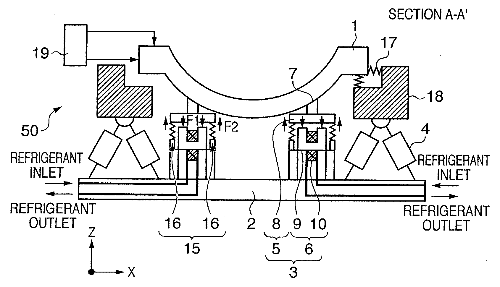
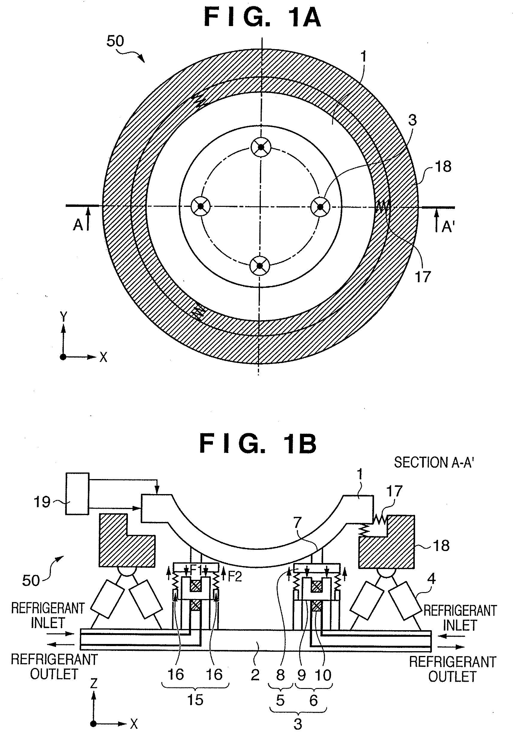
[0034]FIGS. 1A and 1B are views showing a reflecting apparatus according to the first embodiment. FIG. 1A is a top view, and FIG. 1B is a sectional view taken along a line A-A′ in FIG. 1A.

[0035]A reflecting apparatus 50 comprises a mirror 1 having a concave reflecting surface, and a base 2 for supporting the mirror 1. The reflecting apparatus 50 also comprises a plurality of actuators 4 for positioning the mirror 1, a plurality of electromagnet units 3 for deforming the mirror 1, and a plurality of preload units 15. These constituent components 4, 3, and 15 are interposed between the mirror 1 and the base 2.

[0036]A ring-like intermediate member 18 holds the mirror 1 via elastic members 17 that exhibit a spring characteristic. The elastic members 17 are arranged at, e.g., three positions on the circumference of a single circle at an angular interval of 120°. The intermediate member 18 has high rigidity and is driven in the directions of X-, Y-, or Z-axes and the rotational directions...


PUM

PropertyMeasurementUnit
wavelengthaaaaaaaaaa

Abstract

A reflecting apparatus includes a first actuator to position a mirror and a second actuator to deform the mirror. The second actuator includes a magnetic member attached to the mirror, and an electromagnet arranged to oppose the magnetic member in a noncontact manner. The reflecting apparatus can suppress heat generation by the actuator used to deform the surface contour of the mirror, thereby accurately deforming the surface shape of the mirror.

Description

BACKGROUND OF THE INVENTION[0001]1. Field of the Invention[0002]The present invention relates to a reflecting apparatus and, more particularly, to a reflecting apparatus s which constitutes a part of a projection optical system of an exposure apparatus.[0003]2. Description of the Related Art[0004]Conventionally, in photolithography for manufacturing, e.g., a semiconductor element, the pattern formed on the mask (or reticle) is projected and transferred by exposure onto a photosensitive substrate such as a wafer via a projection optical system. In this projection exposure, a projection exposure apparatus such as a step & repeat exposure apparatus (so-called stepper) or a step & scan exposure apparatus (so-called scanner) is used.[0005]An apparatus of this conventional type adopts exposure light such as a g-line (wavelength: 436 nm) or i-line (wavelength-365 nm). These days, the apparatus often adopts, e.g., KrF excimer laser light (wavelength: 248 nm) or ArF excimer laser light (wave...

Claims


Application Information

Patent Timeline
Patent Type & Authority Applications(United States)
IPC IPC(8): G11B7/00
CPCG02B26/0825G03F7/70266G03F7/702G03F7/70233
Inventor UCHIDA, SHINJI
Owner CANON KK
Why Eureka
Try Eureka