
Base Station, Mobile Station and Mobile Communication Method

a mobile station and base station technology, applied in the field of base station, mobile station and mobile communication method, can solve the problems of deteriorating transmission speed of downlink burst, higher reception processing of dl-map by wimax compatible mobile station ss, etc., and achieve the effect of increasing the proportion of dl-map in the frame structure and improving the reception probability of dl-map

Active Publication Date: 2007-12-13
KYOCERA CORP
View PDF8 Cites 40 Cited by
  • Summary
  • Abstract
  • Description
  • Claims
  • Application Information

AI Technical Summary

Benefits of technology

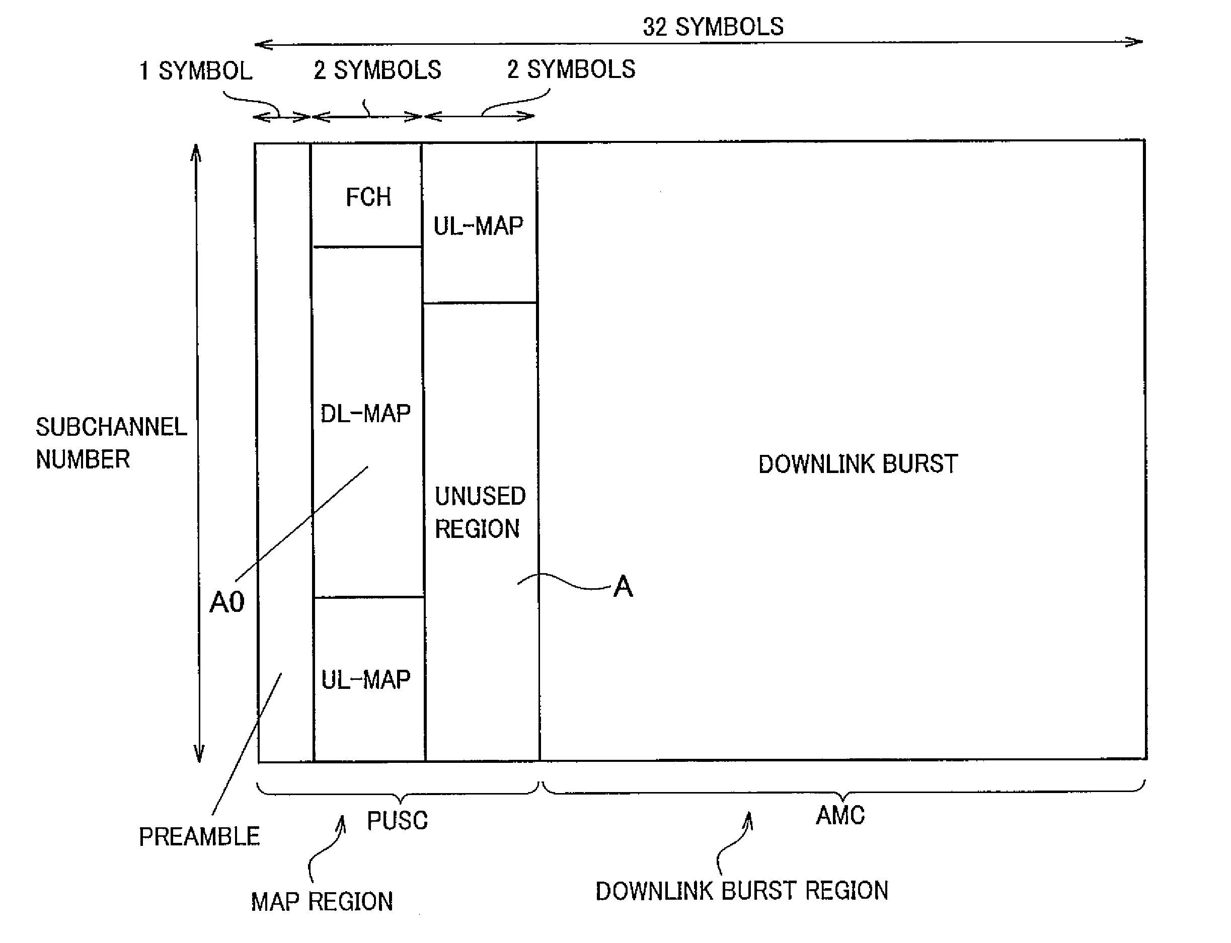
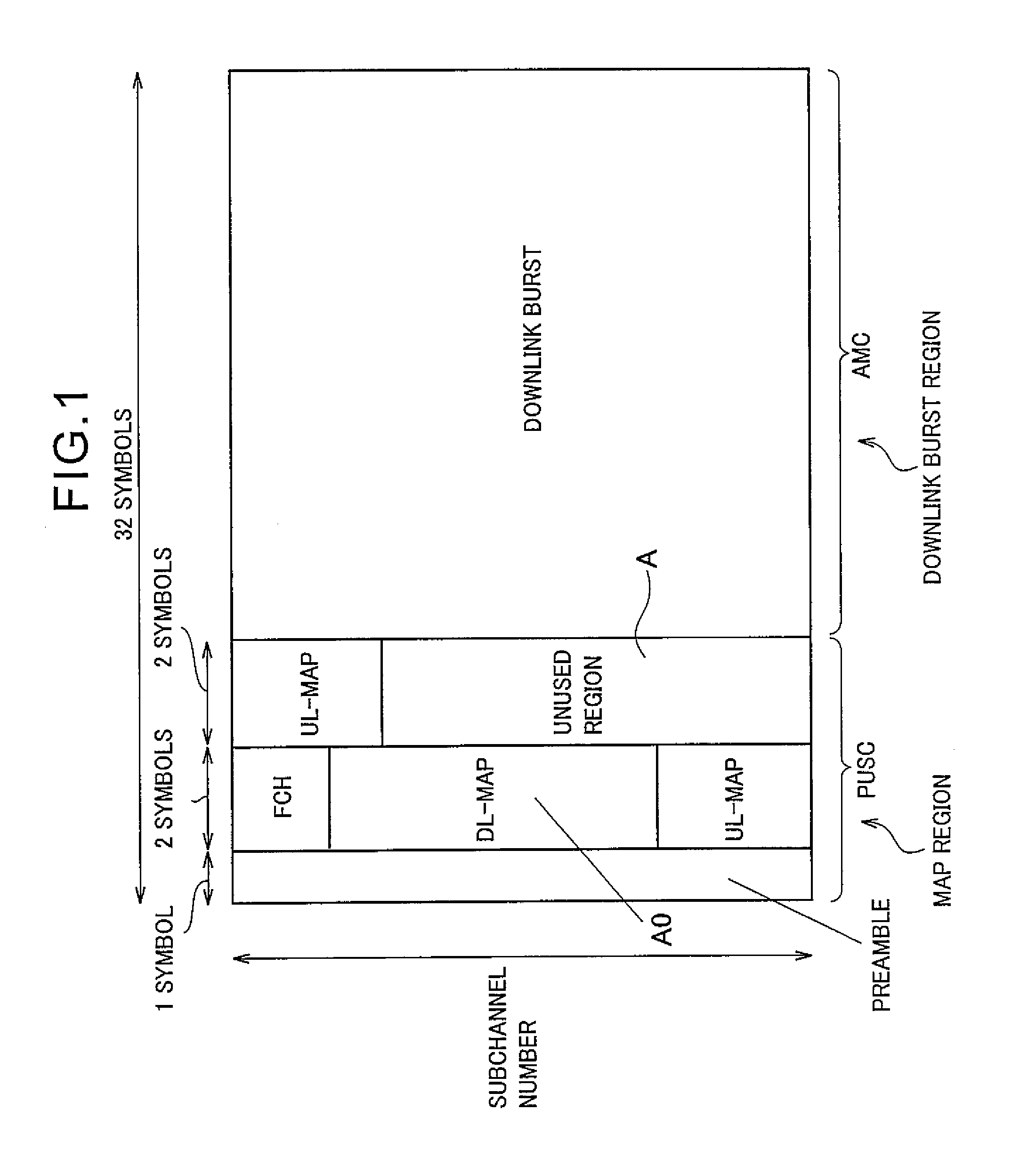
The present invention provides a base station, mobile station, and mobile communication method that can improve the reception probability of DL-MAP without substantially increasing the proportion of DL-MAP in a frame structure. This is achieved by reallocating unused regions in the frame structure to allocate the allocation information of the downlink burst as transmission information. The mobile station receives the downlink burst and decodes it based on the allocation information. The technical effect is to improve the reliability of the downlink burst transmission.

Problems solved by technology

However, in the above-described mobile communication system, there is a problem in that the WiMAX compatible mobile station SS cannot determine the position in the downlink burst region where the downlink burst is allocated, if the WiMAX compatible mobile station SS fails in reception processing of the DL-MAP transmitted from the WiMAX compatible base station BS, and therefore cannot receive the downlink burst.
Accordingly, there is a problem in that a possibility of failure in the reception processing of the DL-MAP by the WiMAX compatible mobile station SS is higher than a possibility of failure in the reception processing of the downlink burst by the WiMAX compatible mobile station SS.
As a consequence, the transmission speed of the downlink burst is deteriorated.

Method used


Image

  • Base Station, Mobile Station and Mobile Communication Method
  • Base Station, Mobile Station and Mobile Communication Method
  • Base Station, Mobile Station and Mobile Communication Method

Examples


first embodiment

Configuration of a Mobile Communication System According to the Present Invention

[0045] A configuration of a mobile communication system according to a first embodiment of the present invention will be described with reference to FIG. 4 to FIG. 12. As shown in FIG. 4, a mobile communication system of this embodiment includes a WiMAX compatible mobile state SS and a WiMAX compatible base station BS.

[0046] Specifically, as shown in FIG. 4, the WiMAX compatible base station BS is configured to transmit transmission information in a downlink burst region (such as a downlink burst), to each WiMAX compatible mobile station SS with a directional beam by use of an AAS.

[0047] Moreover, the WiMAX compatible base station BS is configured to transmit transmission information in a MAP region (much as DL-MAP), to all the WiMAX compatible mobile stations SS located in the area managed by the WiMAX compatible base station BS with a non-directional beam instead of using the AAS.

[0048] The WiMAX c...

second embodiment

OF THE PRESENT INVENTION

[0121] A second embodiment of the present invention will be described with reference to FIG. 15 to FIG. 18. The following description will mainly focus on differences of the second embodiment of the present invention from the first embodiment.

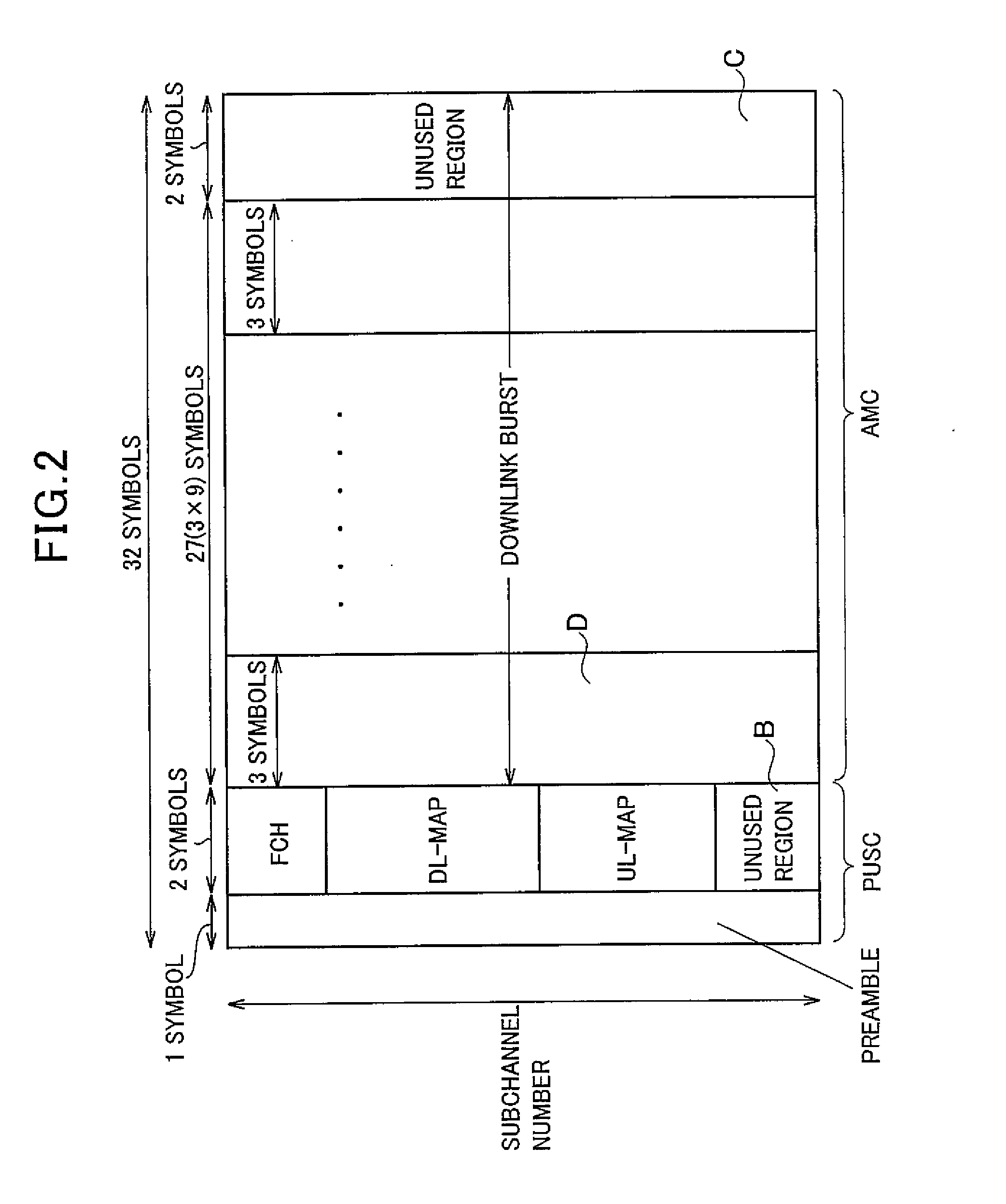
[0122] As shown in FIG. 2, a MAP region allocator unit 10B of a WiMAX compatible base station BS of this embodiment is configured to detect an unused region B that is a region where no transmission information (the preamble, the FCH, the DL-MAP, and the UL-MAP) is allocated in a MAP region after allocating the transmission information to the MAP region, and to detect an unused region C that is a region where no transmission information (downlink bursts addressed to a plurality of WiMAX compatible mobile stations SS) is allocated in a downlink burst region after allocating the transmission information to the downlink burst region.

[0123] In this case, as shown in FIG. 15, the MAP region allocator unit 100 is configured t...

third embodiment

OF THE PRESENT INVENTION

[0154] A third embodiment of the present invention will be described with reference to FIG. 19 to FIG. 22. The following description will mainly focus on differences of the third embodiment of the present invention from the first embodiment and the second embodiment.

[0155] As shown in FIG. 3, a MAP region allocator unit 10B of a WiMAX compatible base station BS of this embodiment is configured to detect an unused region B that is a region where no transmission information (the preamble, the FCH, the DL-MAP, and the UL-MAP) is allocated in a MAP region after allocating the transmission information to the MAP region.

[0156] And, the MAP region allocator unit 10B is configured to detect an unused region E that is a region where no transmission information (downlink bursts addressed to a plurality of WiMAX compatible mobile stations SS) is allocated in a downlink burst region after allocating the transmission information to the downlink burst region.

[0157] Here...


PUM


Abstract

A WiMAX compatible base station (BS) includes: an allocator unit (10B, 10C) configured to allocate allocation information of the downlink burst (DL-MAP) as transmission information in a first region (MAP region), and to allocate the downlink burst as transmission information in the second region (downlink burst region); and a transmitter unit (10F) configured to transmit the allocation information of the downlink burst with a non-directional beam, and to transmit the downlink burst with a non-directional beam or a directional beam. When detecting an unused region (A) where no transmission information is allocated after allocating the transmission information in the first region and the second region in the frame structure, the allocator unit is configured to reallocate, by use of the detected unused region, the allocation information of the downlink burst as the transmission information in the first region.

Description

CROSS REFERENCE TO RELATED APPLICATION [0001] This application is based upon and Claims the benefit of priority from the U.S. Provisional Application No. 60 / 812,237, filed on Jun. 9, 2006; the entire contents of which are incorporated herein by reference. [0002] The entire contents of “IEEE Standard for Local and Metropolitan Area Networks Part 16: Air Interface for Fixed Broadband Wireless Access Systems (IEEE Std 802.16-2004), Oct. 1, 2004”, and “IEEE Standard for Local and Metropolitan Area Networks Part 16: Air Interface for Fixed and Mobile Broadband Wireless Access Systems Amendment 2: Physical and Medium Access Control Layers for Combined Fixed and Mobile Operation in Licensed Bands and Corrigendum 1 (IEEE Std 802-16e-2005), February, 2006” are incorporated in this application by reference.BACKGROUND OF THE INVENTION [0003] 1. Field of the Invention [0004] The present invention relates to: a mobile communication method for transmitting a downlink burst from a base station to ...

Claims


Application Information

Patent Timeline
Patent Type & Authority Applications(United States)
IPC IPC(8): H04Q7/00H04W72/04
CPCH04W72/042H04W72/23
Inventor INOHIZA, HIROHIKO
Owner KYOCERA CORP
Learn More