
Method and apparatus for improving quality of composite video signal and method and apparatus for removing artifact of composite video signal

a composite video and burst signal technology, applied in the field of improving picture quality in can solve the problems of ineffective improvement of picture quality by the related art apparatus, deterioration of picture quality, and noise having a color component in addition to the luminance signal noise, etc., to achieve the effect of improving picture quality in the composite video burst signal

Inactive Publication Date: 2007-12-13
IND UNIV COOP FOUND SOGANG UNIV +1
View PDF0 Cites 31 Cited by
  • Summary
  • Abstract
  • Description
  • Claims
  • Application Information

AI Technical Summary

Benefits of technology

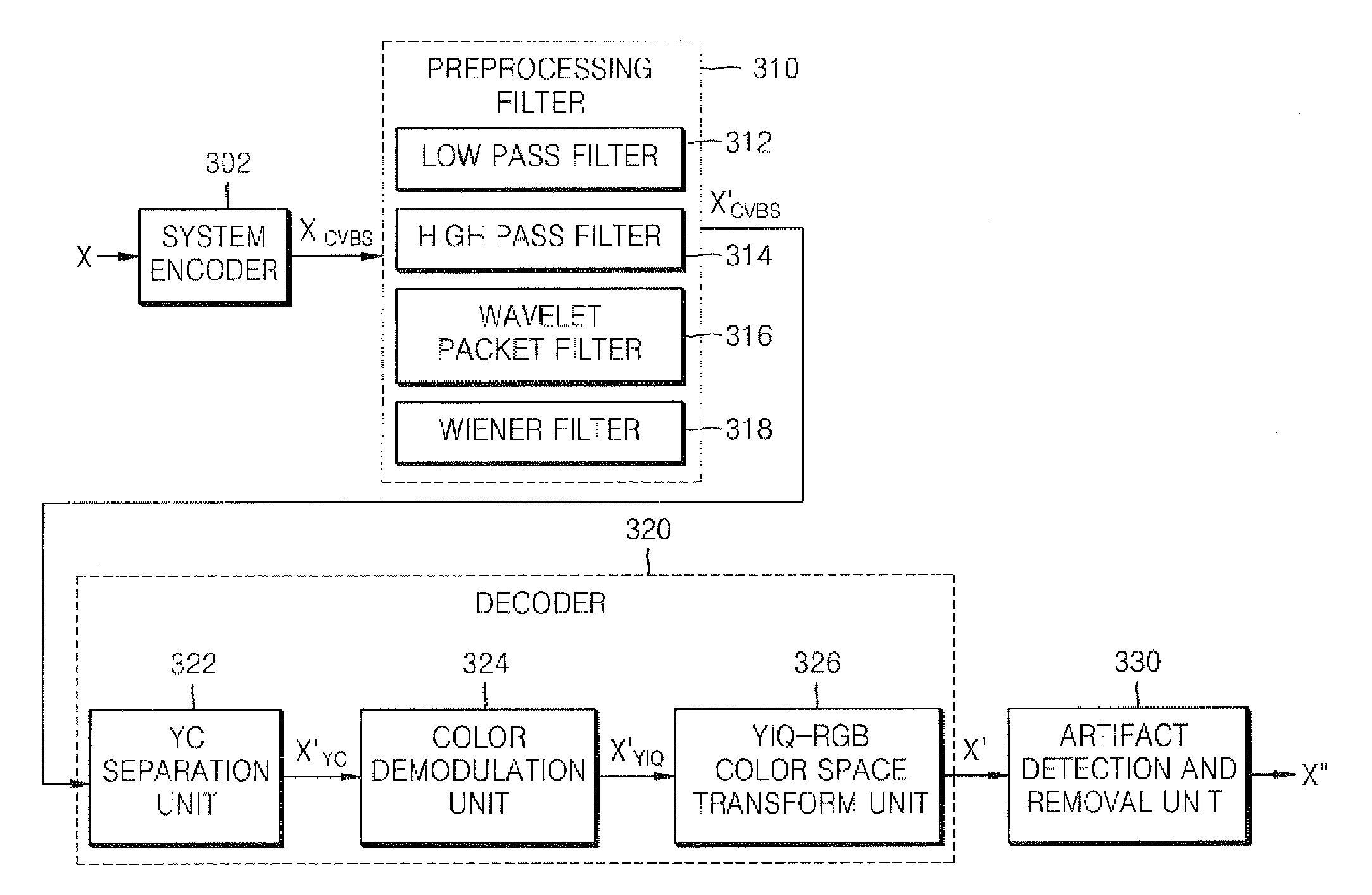
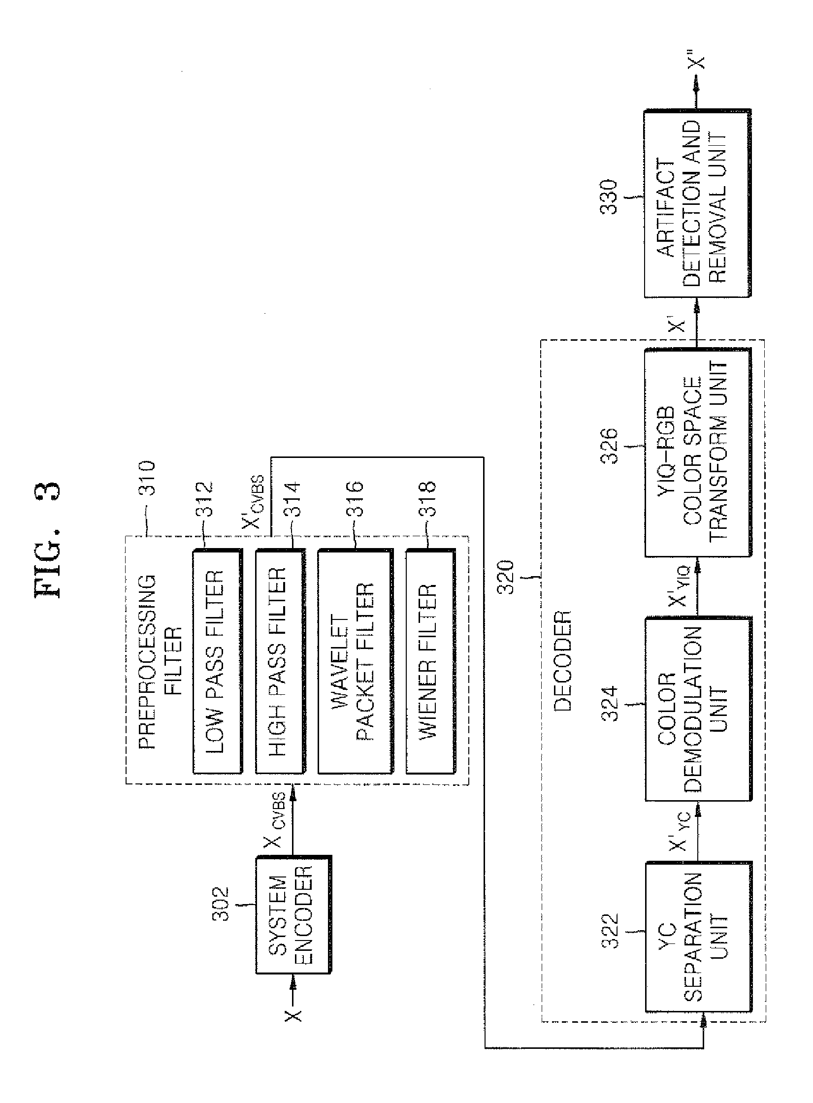
[0012]The present invention provides a method and apparatus for improving picture quality in a composite video burst signal, and a method and apparatus for removing artifacts in a composite video burst signal, in which a filter is disposed before decoding is performed, and through preprocessing, noise in a 1-dimensional signal is removed and by using a variety of artifact detection and removal methods, picture quality is improved.
[0013]According to an aspect of the present invention, there is provided a method of improving picture quality in a composite video burst signal including dividing the composite video burst signal into a plurality of frequency bands by using a low pass filter and a high pass filter, performing wavelet packet filtering of bands including a chrominance signal higher than a specified threshold among the divided plurality of frequency bands, and performing Wiener filtering of bands including a chrominance signal lower than a specified threshold.
[0023]According to another aspect of the present invention, there is provided an apparatus for improving picture quality in a composite video burst signal including a preprocessing filter performing filtering of the composite video burst signal by using a wavelet packet filter and a Wiener filter, a YC separation unit separating the filtered composite video burst signal into a luminance signal and a chrominance signal, a color demodulation unit separating the chrominance signal into an in-phase signal and an orthogonal-phase signal, and a YIQ-RGB color space transform unit transforming the filtered luminance signal, in-phase signal and orthogonal-phase signal into an R signal, a G signal, and a B signal, respectively, in RGB space, and outputting an output video signal.

Problems solved by technology

Accordingly, noise having a variety of colors as well as noise having black and white colors appears, and the picture quality deteriorates.
However, in the case of actual noise occurring in the process of transmitting and receiving a television signal, noise is added in the process of transforming signals into a composite video burst signal, and thus, noise having a color component is generated in addition to the luminance signal noise.
The related art apparatus for improving picture quality cannot apply an appropriate algorithm to this noise, and thus, the improvement of picture quality by the related art apparatus is not effective.

Method used


Image

  • Method and apparatus for improving quality of composite video signal and method and apparatus for removing artifact of composite video signal
  • Method and apparatus for improving quality of composite video signal and method and apparatus for removing artifact of composite video signal
  • Method and apparatus for improving quality of composite video signal and method and apparatus for removing artifact of composite video signal

Examples


Embodiment Construction

[0059]The present invention will now be described more fully with reference to the accompanying drawings, in which exemplary embodiments of the invention are shown.

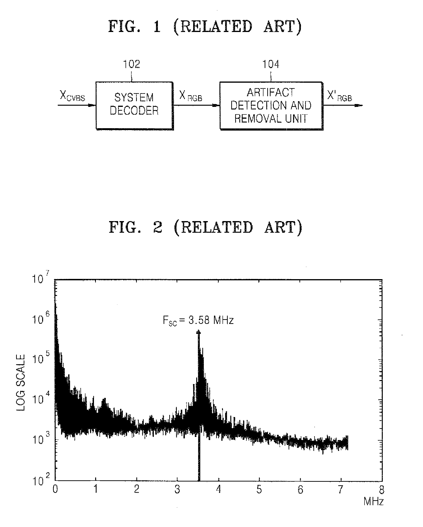
[0060]As illustrated in FIG. 2, a composite video burst signal includes an in-phase signal (I signal) and an orthogonal-phase signal (Q signal) with a color subcarrier frequency Fsc (3.58 Mhz) at the center. Accordingly, the composite video burst signal has a form in which a luminance signal, an in-phase signal and an orthogonal-phase signal are added as shown in equation 1 below. The luminance signal (Y signal) is positioned in low frequency bands and the chrominance signal (C signal) is positioned in high frequency bands:

CVBS=Y+C=Y+Icos(Fsct)+Qsin(Fsct)(1)

[0061]Thus, the composite video burst signal has much information in the low frequency bands but also has much information around 3.58 Mhz where the chrominance signal is positioned. Accordingly, the ordinary noise removal technique by which a high frequency band is re...


PUM


Abstract

A method of improving picture quality in a composite video burst signal includes dividing the composite video burst signal into a plurality of frequency bands using a low pass filter and a high pass filter, performing wavelet packet filtering of frequency bands including a chrominance signal having energy higher than a specified threshold among the plurality of frequency bands, and performing Wiener filtering of frequency bands including a chrominance signal having energy lower than a specified threshold.

Description

CROSS-REFERENCE TO RELATED PATENT APPLICATIONS[0001]This application claims priority to Korean Patent Application No. 10-2006-0052873, filed on Jun. 13, 2006, in the Korean Intellectual Property Office, the disclosure of which is incorporated herein in its entirety by reference.BACKGROUND OF THE INVENTION[0002]1. Field of the Invention[0003]Methods and apparatuses consistent with the present invention relate to improving picture quality in a composite video burst signal, and removing artifacts in a composite video burst signal.[0004]2. Description of the Related Art[0005]In a process of encoding video information in a National Television System Committee (NTSC) system, a signal is encoded such that a luminance signal is modulated onto the low frequency part of the signal, and a chrominance signal is modulated onto the high frequency part of the signal. This signal is called a composite video burst signal (CVBS), and through a transmission and reception process, white Gaussian noise ...

Claims


Application Information

Patent Timeline
Patent Type & Authority Applications(United States)
IPC IPC(8): H04N11/02
CPCH04N19/51H04N19/86H04N19/80H04N19/186H04N9/64H04N9/77
Inventor KIM, SUNG-HEEYANG, SEUNG-JOONPARK, RAE-HONGLEE, JI-WONLEE, HYUN-SEUNGKIM, JUN-YOUNGLIM, BO-RA
Owner IND UNIV COOP FOUND SOGANG UNIV
Learn More