Electric motor

a technology of electric motors and motors, applied in the direction of dynamo-electric machines, electrical apparatus, magnetic circuits, etc., can solve the problems of reducing the efficiency of the motor, reducing the power of the motor, and the method is relatively cumbersome and unreliable, so as to achieve optimum efficiency, simple assembly, and robust structure

Inactive Publication Date: 2007-12-13
BUHLER MOTOR GMBH
View PDF13 Cites 22 Cited by
  • Summary
  • Abstract
  • Description
  • Claims
  • Application Information

AI Technical Summary

Benefits of technology

[0006] It is therefore, the object of the invention to provide an electric motor, in which the stator is composed of the least number of components, requires simple ...

Problems solved by technology

The achievable power of such motors is therefore limited and it is sometimes necessary to arrange a plurality of stators in succession.
This method is...

Method used


Image

  • Electric motor
  • Electric motor
  • Electric motor

Examples


first embodiment

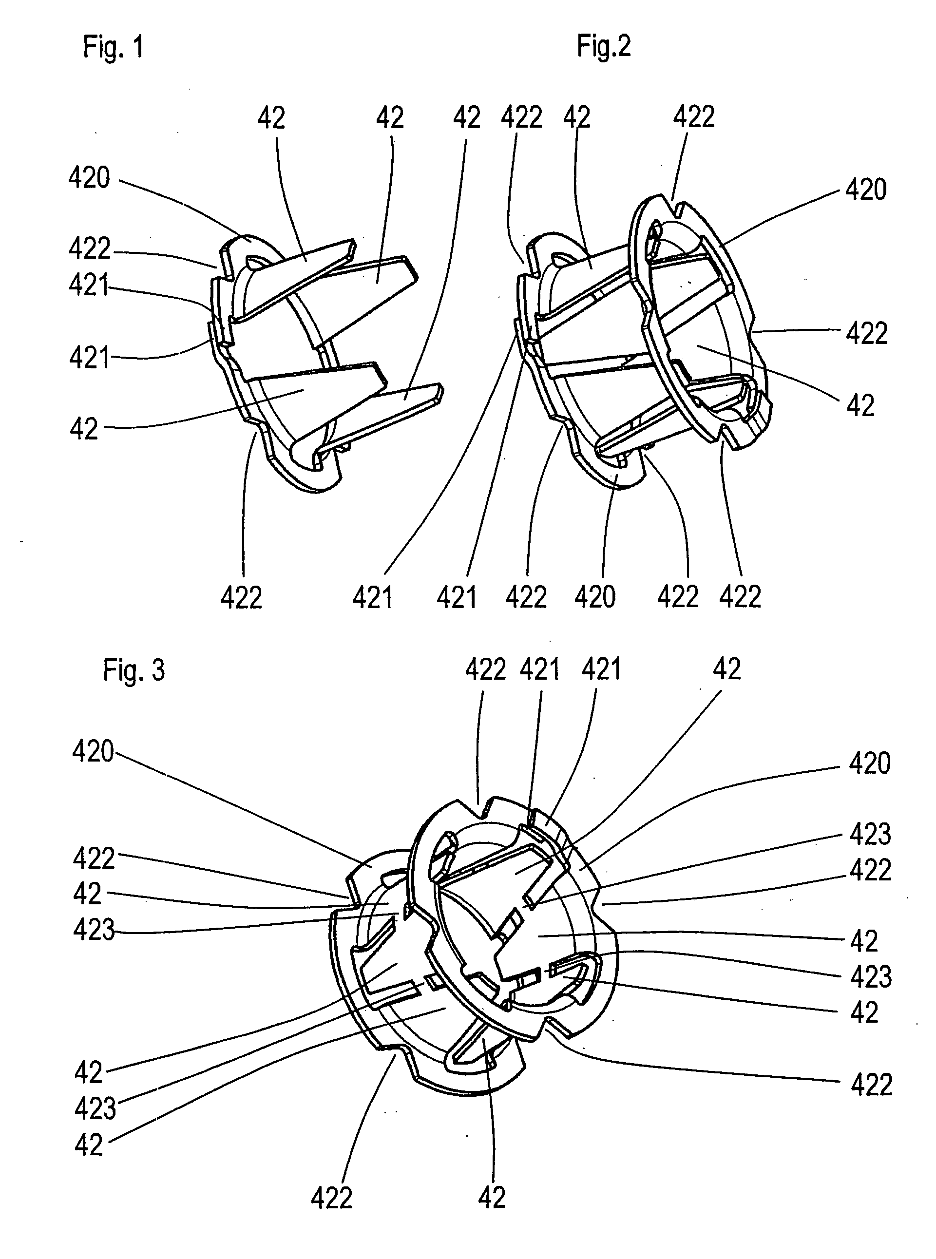
[0031]FIG. 2 shows a first embodiment with two ring disc-shaped stator plates 420 with their claw poles 42 facing one another, wherein each claw pole 42 of the first stator plate 420 follows a claw pole of the second stator plate 420. Both the stator plates 420 are shown in their correct positions; however they are not in contact with one another. In the installation state, the stator plates are held by means of an insulating body. The insulating body is made of injection-molded plastic material and is molded around the stator plates for this purpose, wherein connecting means and fixing means are also formed additionally.

second embodiment

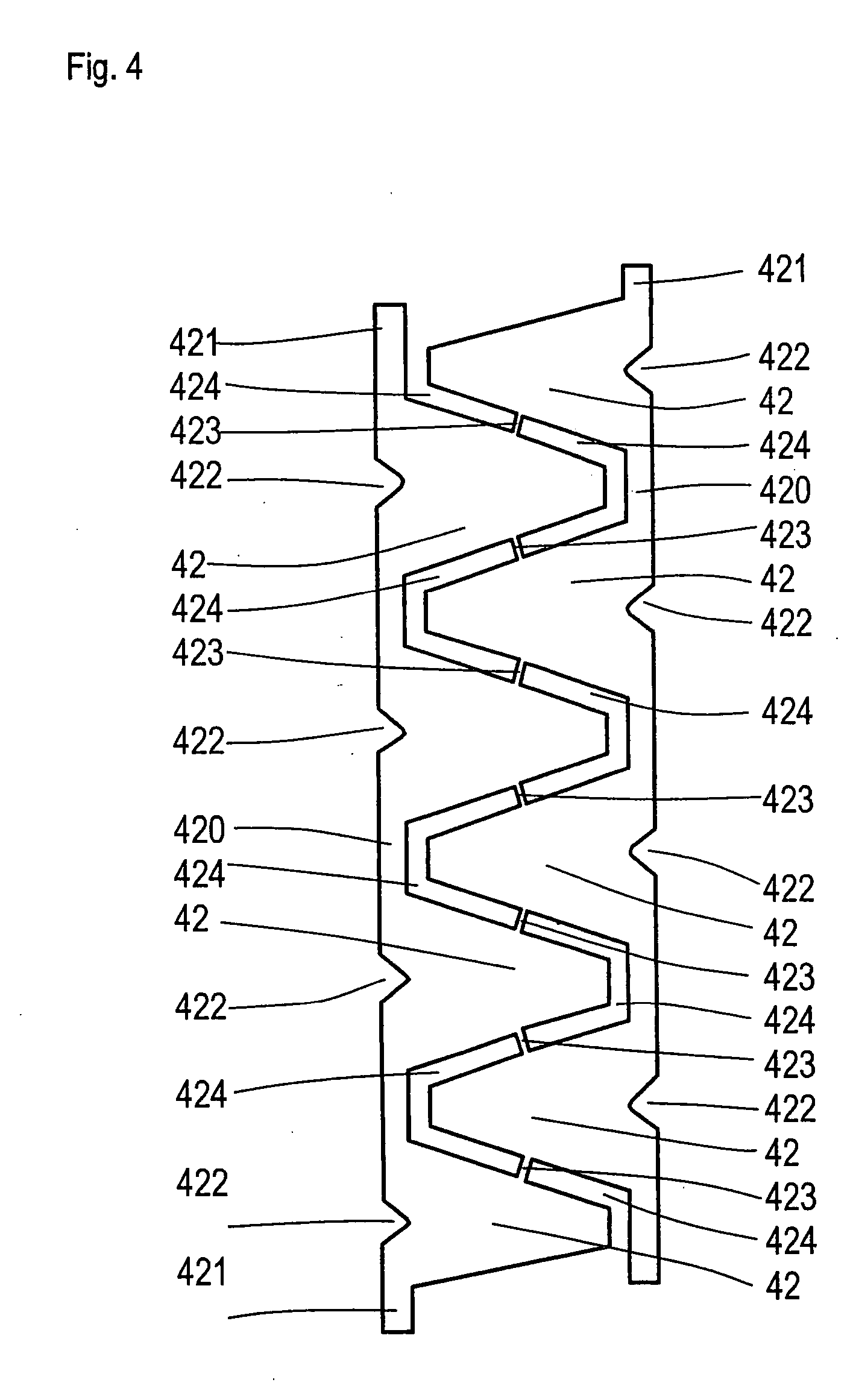
[0032]FIG. 3 shows the invention, in which the stator plates 420 with the claw poles 42 are punched out of a single sheet-metal strip, the claw poles 42 being connected to one another by means of sheet-metal bridges 423. The sheet-metal bridges can remain in the stator in the final assembly state if they are designed to be sufficiently thin. However, they reduce the efficiency of the motor. It would be more advantageous here to remove the bridges. This is associated with higher production expenditure. The geometry of the stator with the exception of the sheet-metal bridges 423 corresponds to the arrangement shown in FIG. 2. Two claw poles 42 are not connected to one another by means of sheet-metal bridges; instead they form the ends of said sheet-metal strip. The ends 421 of the ring disc-shaped stator plates 420 are welded to one another similarly to FIGS. 1 and 2. The welding can be carried out in a welding unit in which the inner diameter of the claw pole ring is calibrated.

[0033...


PUM

PropertyMeasurementUnit
Lengthaaaaaaaaaa
Diameteraaaaaaaaaa
Flexibilityaaaaaaaaaa

Abstract

The invention relates to an electric motor comprising a permanent magnet rotor, which is supported rotationally about a central axis, a wound stator having a cylinder ring-shaped stator winding, claw poles, which are disposed perpendicularly to ring disc-shaped stator plates and around the central axis, and a cylinder jacket-shaped yoke ring, the length of the claw poles in the axially parallel direction being clearly greater than half the inner diameter of the stator. It is the object of the invention to provide an electric motor, in which the stator is composed of the least number of components, requires simple assembly and has a robust structure and optimum efficiency, thereby enabling greater design flexibility, usability of installation space and thus an economic construction. This objective is solved according to the invention in that the magnetically conductive part of the stator comprises a cylinder jacket-shaped yoke ring and two ring disc-shaped stator plates, the stator plates are each designed as a single piece with a plurality of claw poles and the ring disc-shaped stator plates comprise ends, which are connected to one another.

Description

BACKGROUND OF THE INVENTION [0001] (1) Field of the Invention [0002] The invention relates to an electric motor comprising a permanent magnet rotor, which is supported rotationally about a central axis, a wound stator having a cylinder ring-shaped stator winding, claw poles, which are disposed perpendicularly to ring disc-shaped stator plates and around the central axis, and a cylinder jacket-shaped yoke ring, the length of the claw poles in the axially parallel direction being clearly greater than half the inner diameter of the stator. [0003] (2) Description of the Related Art [0004] The most common manner of producing claw pole stators consists in bending off the pre-punched claws from the center of a disc perpendicularly thereto. In this manner the maximum length of the claws in the axial direction is limited to approx. half the inner diameter of the stator. The achievable power of such motors is therefore limited and it is sometimes necessary to arrange a plurality of stators in...

Claims


Application Information

Patent Timeline
IPC IPC(8): F04B17/03H02K11/00H02K15/02H02K21/12H02K3/30
CPCY10T29/49009H02K1/145
Inventor IHLE, OLAIPETERREINS, THOMAS
Owner BUHLER MOTOR GMBH
Why Eureka
Try Eureka