Communication system, communication apparatus, communication method and computer program

Active Publication Date: 2007-12-13
SONY CORP
View PDF9 Cites 55 Cited by
  • Summary
  • Abstract
  • Description
  • Claims
  • Application Information

AI Technical Summary

Benefits of technology

[0047]In accordance with the present invention, there is provided an excellent communication system in which, in a power save mode, a radio communication terminal makes a transition from a doze mode to an awake mode for receiving beacon frames, which are broadcasted by a radio communication base station at predetermined beacon intervals determined in advance, at a rate also determined in advance and requests the radio communication base station to transmit data received from another radio communication terminal for the radio communication terminal and held in the radio communication base station as data destined for the radio communication terminal to the radio communication terminal in order to carry out a stable communication of the data with the other radio communication terminal, and provided radio communication apparatus to serve as the radio communication terminals and the radio communication base station, a radio communication method to be adopted by the radio communication apparatus as well as a computer program implementing the radio communication method.
[0048]In addition, also in accordance with the present invention, there is provided an excellent communication system capable of carrying out stable communications of data and well preventing a power saving function from deteriorating by avoiding collisions of notice frames transmitted by radio communication terminals in a state of contending with each other for the radio communication medium as notice frames each used for showing a transition from the doze state to the awake state and a demand for a transmission of data from the base station without requiring the radio communication base station to carry out special operations even if the number of radio communication terminals connected to the radio communication base station increases, and provided a radio communication apparatus to serve as the radio communication terminals and the radio communication base station, a radio communication method to be adopted by the radio communication apparatus as well as a computer program implementing the radio communication method.
[0049]Thus, the radio communication base station provided by the present invention as a radio communication base station for accommodating radio communication terminals in a cell is no longer required to process a number of notice frames received from radio communication terminals at the same time. That is to say, the load borne by the radio communication bas

Problems solved by technology

In the doze state, on the other hand, the radio communication terminal 0110 operates at low power consumption but is not capable of exchanging data with the radio communication base station 0101.
In addition, if timings taken by the radio communication terminals as timings to make a transition from the doze state to the awake state are concentrated on a specific beacon frame, there is raised a problem that a radio communication terminal is hardly capable of acquiring data held in the radio communication base station during the doze state as data destined for the radio communication terminal.
The increased number of radio communication terminals each transmitting such a notice frame to the radio communication base station means that there is a greater risk of collisions of notice frames contending with each other for the radio communication medium.
In this case, since the radio communication terminal with the notice-frame transmission put in the wait state is also put in a wait state in the awake mode, the radio communication terminal undesirably consumes power in a wasteful manner.
As a result, the power saving effect deteriorates.
In addition, if the number of notice frames each put in a wait state increase to a very large value, it is quite within the bounds of possibility that more wait times set by adoption of the rand

Method used


Image

  • Communication system, communication apparatus, communication method and computer program
  • Communication system, communication apparatus, communication method and computer program
  • Communication system, communication apparatus, communication method and computer program

Examples


Embodiment Construction

[0059]A preferred embodiment of the invention is explained by referring to diagrams as follows.

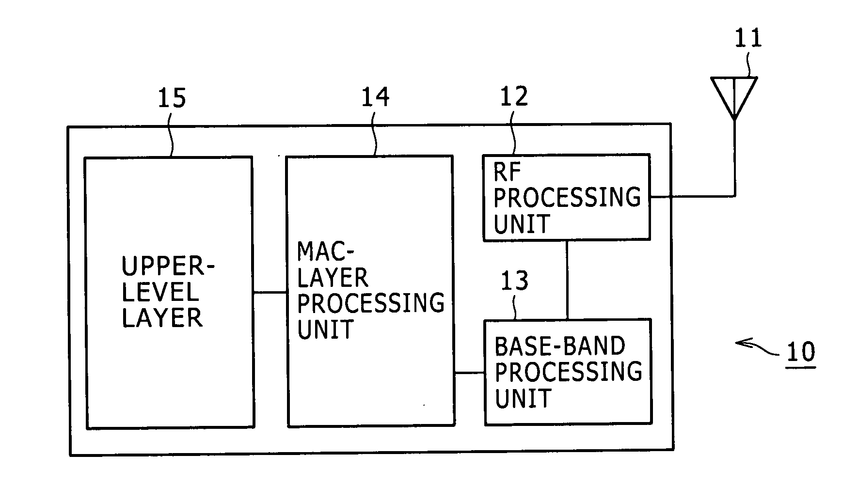
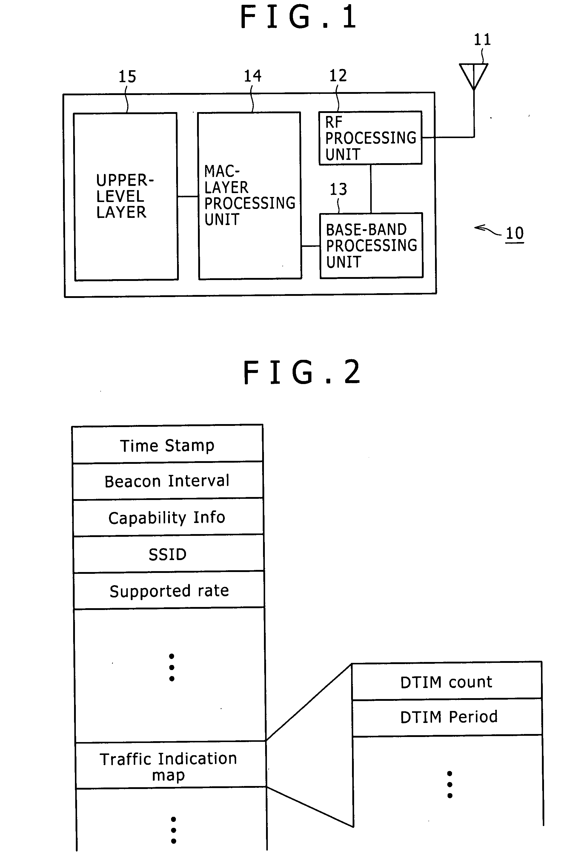
[0060]An embodiment of the present invention assumes a radio communication system, which typically operates in an infrastructure BSS (Base Service Set) mode conforming to the IEEE802.11 standards. In a system of this type, a radio communication base station broadcasts beacon frames at beacon intervals determined in advance in order to control radio communication terminals existing in a cell of the system. Connected to the radio communication base station, the radio communication terminals communicate data to each other by adoption of a so-called random back-off algorithm.

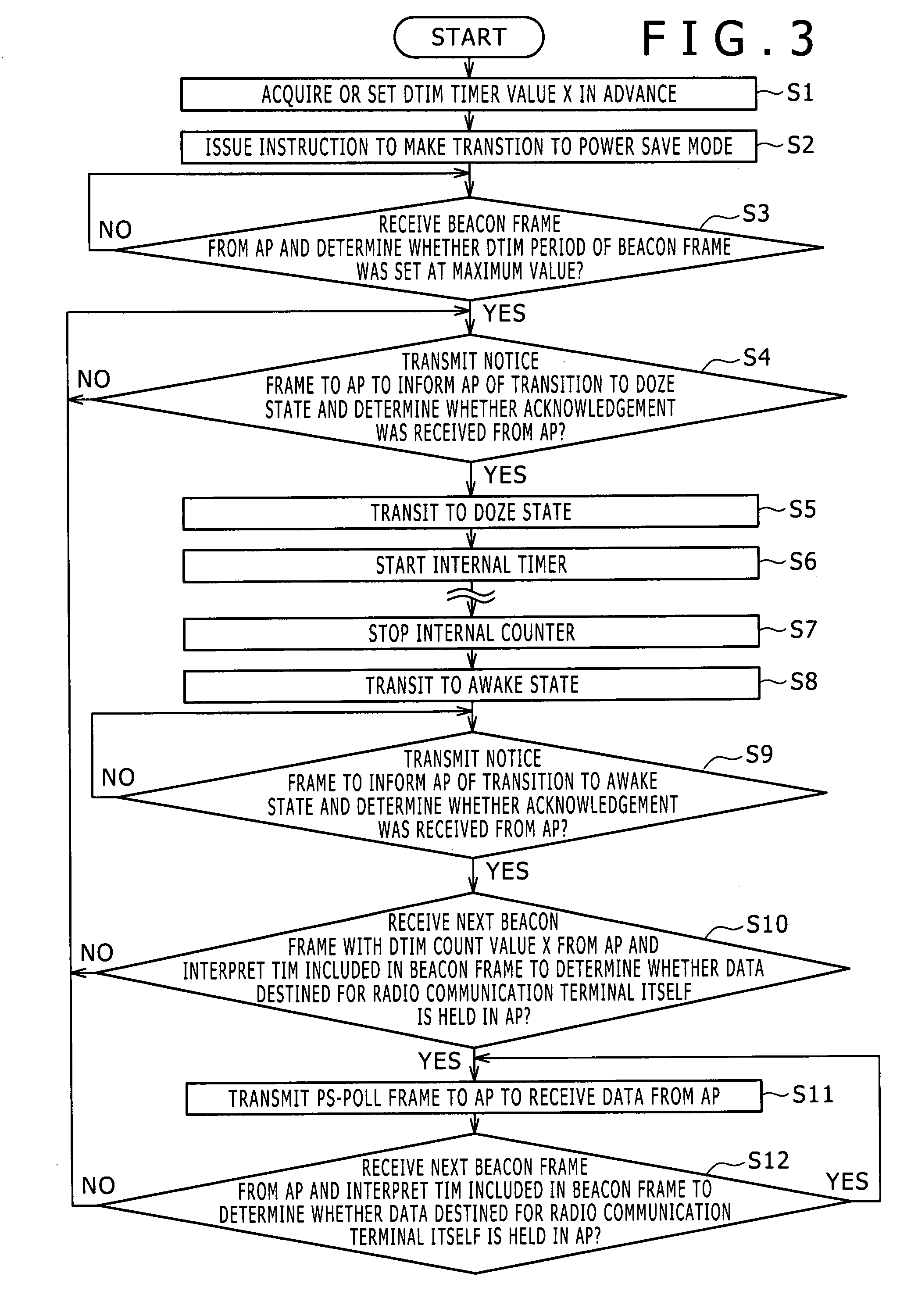
[0061]The IEEE802.11 standards prescribe an active mode and a power save mode. A radio communication terminal put in the power save mode carries out intermittent operations in order to repeatedly make transitions from a doze state to an awake state and vice versa. The doze state is a state in which the operations of at lea...


PUM


Abstract

Disclosed herein is a communication system wherein, non-periodical communications of data are carried out between an information transmitting terminal and one or more information receiving terminals, the information transmitting terminal periodically broadcasts network control information to the information receiving terminals, each of the information receiving terminals receives the network control information from the information transmitting terminal at a rate determined in advance, each of the information receiving terminals receives the network control information from the information transmitting terminal in a fixed-length information acquisition period; and at least some specific ones of the information receiving terminals each arbitrarily shift the starting point of the information acquisition period of the specific information receiving terminal.

Description

CROSS REFERENCES TO RELATED APPLICATIONS[0001]The present invention contains subject matter related to Japanese Patent Application JP 2006-159278 filed in the Japan Patent Office on Jun. 8, 2006, the entire contents of which being incorporated herein by reference.BACKGROUND OF THE INVENTION[0002]1. Field of the Invention[0003]The present invention relates to a communication system connected to a base station and used for communicating data by adoption of a random back-off algorithm, relates to a communication apparatus employed in the communication system, relates to a communication method adopted by the communication apparatus as well as relates to a computer program for implementing the communication method. More particularly, the present invention relates to a communication system for carrying out intermittent operations in order to repeat a doze state and an awake state in a power save mode, relates to a communication apparatus employed in the communication system, relates to a ...

Claims


Application Information

Patent Timeline
IPC IPC(8): H04Q7/20H04W52/02H04W74/08
CPCH04W52/0251Y02B60/50H04W74/08Y02D30/70
Inventor SHIMIZU, HIROYUKI
Owner SONY CORP
Why Eureka
Try Eureka